Overview of maintenance and turning gear products for turbine spindle turning device:
The turbine maintenance turntable is a power device designed and manufactured to meet the requirements of turbine maintenance and spindle rotation. The turbine maintenance turning gear is a process in which the main shaft of the turbine unit needs to be disassembled and repaired before being assembled. When assembling, the main spindle must be kept concentric. Combine and measure the concentricity of the main spindle, and perform necessary technical processing to eliminate errors, so as to achieve the specified concentricity requirements of the main spindle. The measurement of the concentricity of the main shaft is completed through a turning device. The main shaft turning device of the steam turbine is fixed by the gear (referred to as the main shaft gear) that meshes with the starting disc car on the main shaft using the original screw holes and bolts on the body. After starting the reducer, the main shaft of the steam turbine can be slowly and uniformly rotated in a disassembled state (about - revolutions per minute).
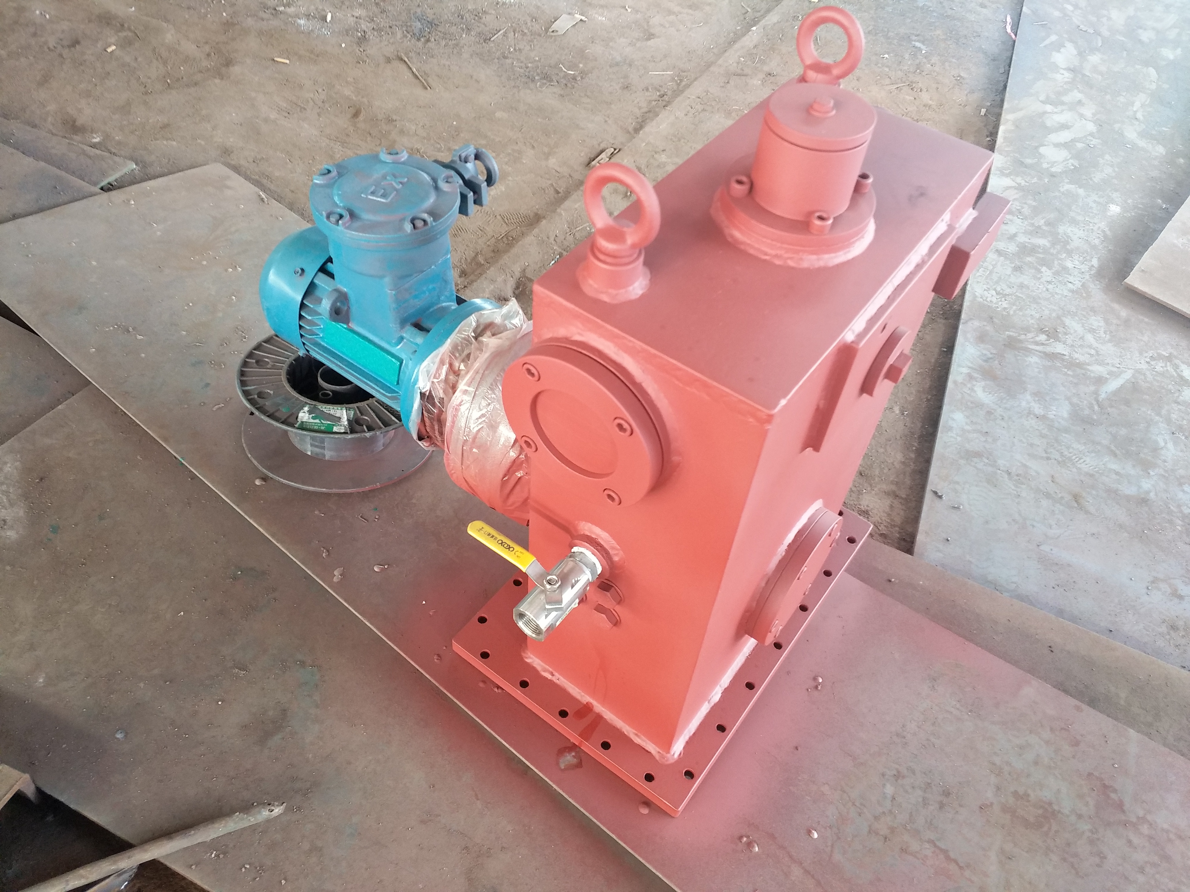
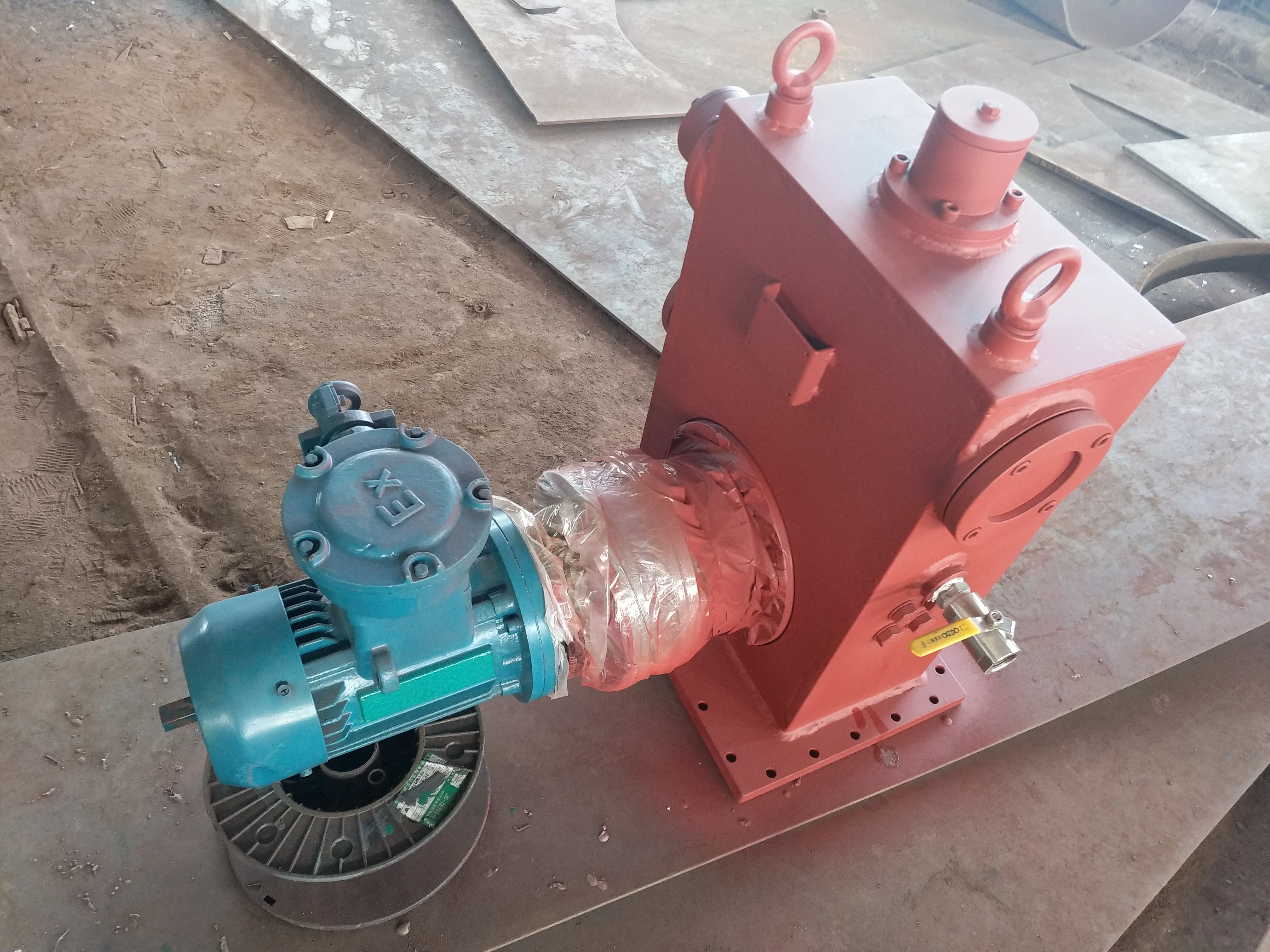
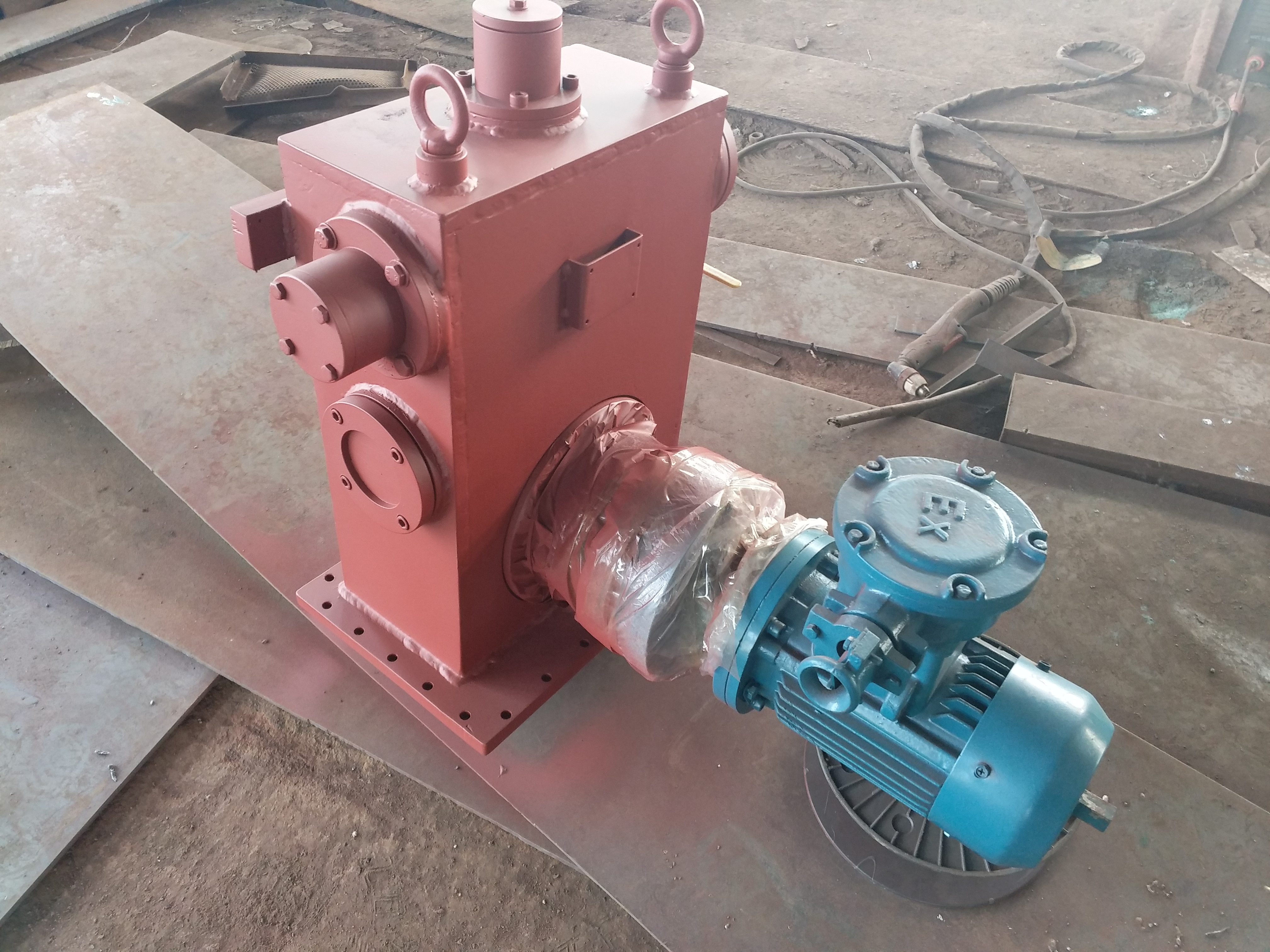
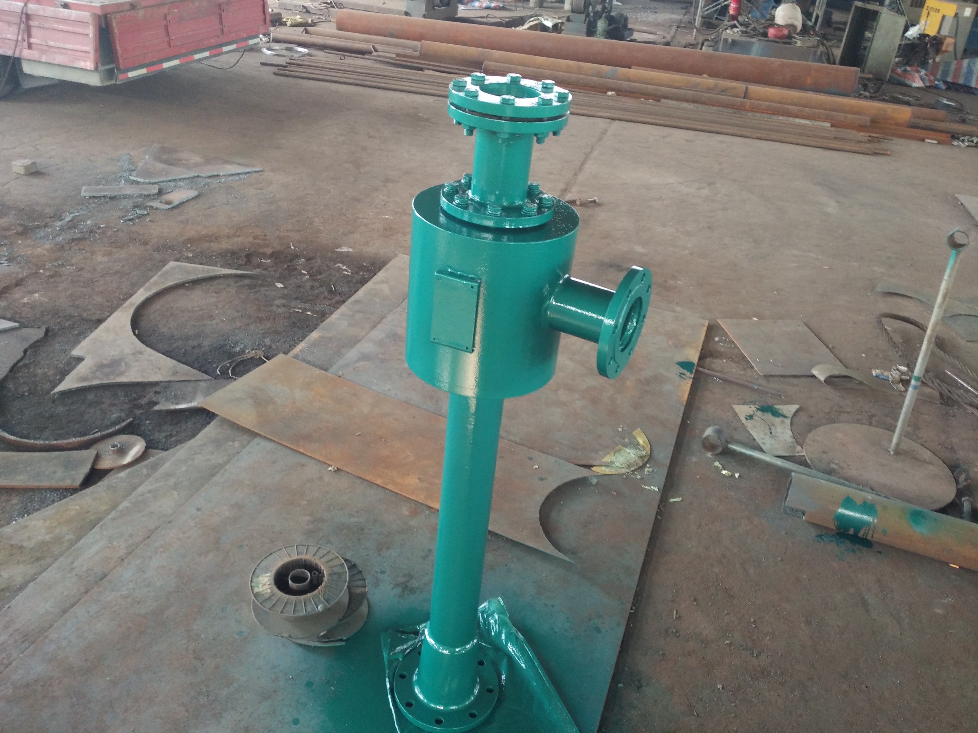
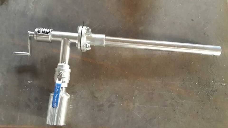
The turbine maintenance disc is a side mounted turbine main shaft maintenance disc turning device, with its body installed on the main shaft side and equipped with a large speed ratio swing pin wheel reducer. The small gear meshes with the main shaft gear to achieve continuous rotation of the main shaft at low speed. This device is small in size, lightweight, easy to install and use, flexible in adjustment, and versatile. It is a maintenance tool for steam turbine units.
Manufacturer of turbine spindle turning device for maintenance and turning gear
The maintenance of the turbine spindle turning device on the turning gear -:
1. Use a speed ratio pendulum needle wheel reducer to achieve low-speed rotation (about 1 rpm)
2. Small size, light weight, easy installation, flexible adjustment, and strong versatility.
3. The turbine maintenance disc is a side mounted turbine spindle maintenance disc crossbeam, which is convenient and accurate for measuring the spindle.
4. High stiffness, stress condition, stable and strong operation.
Side mounted steam turbine - Repair disc turning device -:
1. Other types of spindle turning devices:
The main shaft disc rotation of the steam turbine repair was carried out using a crane and steel wire rope, which has a large measurement error, is time-consuming and labor-intensive, and has unsafe factors. This method is no longer used in most power plants and has been replaced by vertical mechanical equipment.
The purpose of the internal use is to use a screw cross type universal maintenance turntable, and this turntable device is:
(1) Adjustable heart distance, versatile and strong;
(2) The crossbeam is detachable, which is convenient to a certain extent;
(3) Continuous operation with high measurement accuracy.
The maintenance of the turbine spindle turning device lacks the following turning gear:
(1) Every time the main shaft of the steam turbine is lifted out and in, resetting the crossbeam and driving part is cumbersome;
(2) Screw - requires manual adjustment, installation, disassembly, and adjustment, and is prone to work-related accidents when moved in oily and uneven areas;
(3) The crossbeam has certain obstacles to the measurement work;
(4) Active joints - poor fastening and slight vibration;
(5) The motor and reducer have high power, large size, are both bulky and prone to damage to the main engine.
In addition to this type of rotary device, previous rotary devices such as rack and pinion, hydraulic intermittent, bridge, and due to their lack, have not been widely used in power plant maintenance.
2. PZ type side mounted steam turbine spindle turning device:
The maintenance disc car is a spindle disc turning equipment designed and manufactured by summarizing the shortcomings of past and current turbine repair tools and disc turning devices, calculating the power consumption of spindle disc turning, and fully leveraging the favorable on-site conditions. It is as follows:
(1) Adopting side mounted installation. When repairing and lifting the main shaft of the steam turbine, it is not necessary to disassemble any components of the device (adjust the screw appropriately to move the body backwards);
(2) When repairing the crossbeam and spindle, it is convenient and accurate to observe and display;
(3) High stiffness, stress condition, stable and strong operation;
(4) Small in size and overall - convenient for storage and storage;
(5) Universal Strong.
The working principle of the maintenance disc for the main shaft turning device of the steam turbine:
The main shaft turning device of a steam turbine is a power device designed and manufactured to meet the requirements of turbine unit maintenance and main shaft turning. During the maintenance process of the steam turbine unit, the main shaft needs to be disassembled and repaired before being assembled. When assembling, the main spindle must be kept concentric. Combine and measure the concentricity of the main spindle, and perform necessary technical processing to eliminate errors, so as to achieve the specified concentricity requirements of the main spindle. The measurement of the concentricity of the main shaft is completed through a turning device. The main shaft turning device of the steam turbine is fixed by the gear (referred to as the main shaft gear) that meshes with the starting disc car on the main shaft using the original screw holes and bolts on the body. After starting the reducer, the main shaft of the steam turbine can be slowly and uniformly rotated in a disassembled state (about - revolutions per minute).
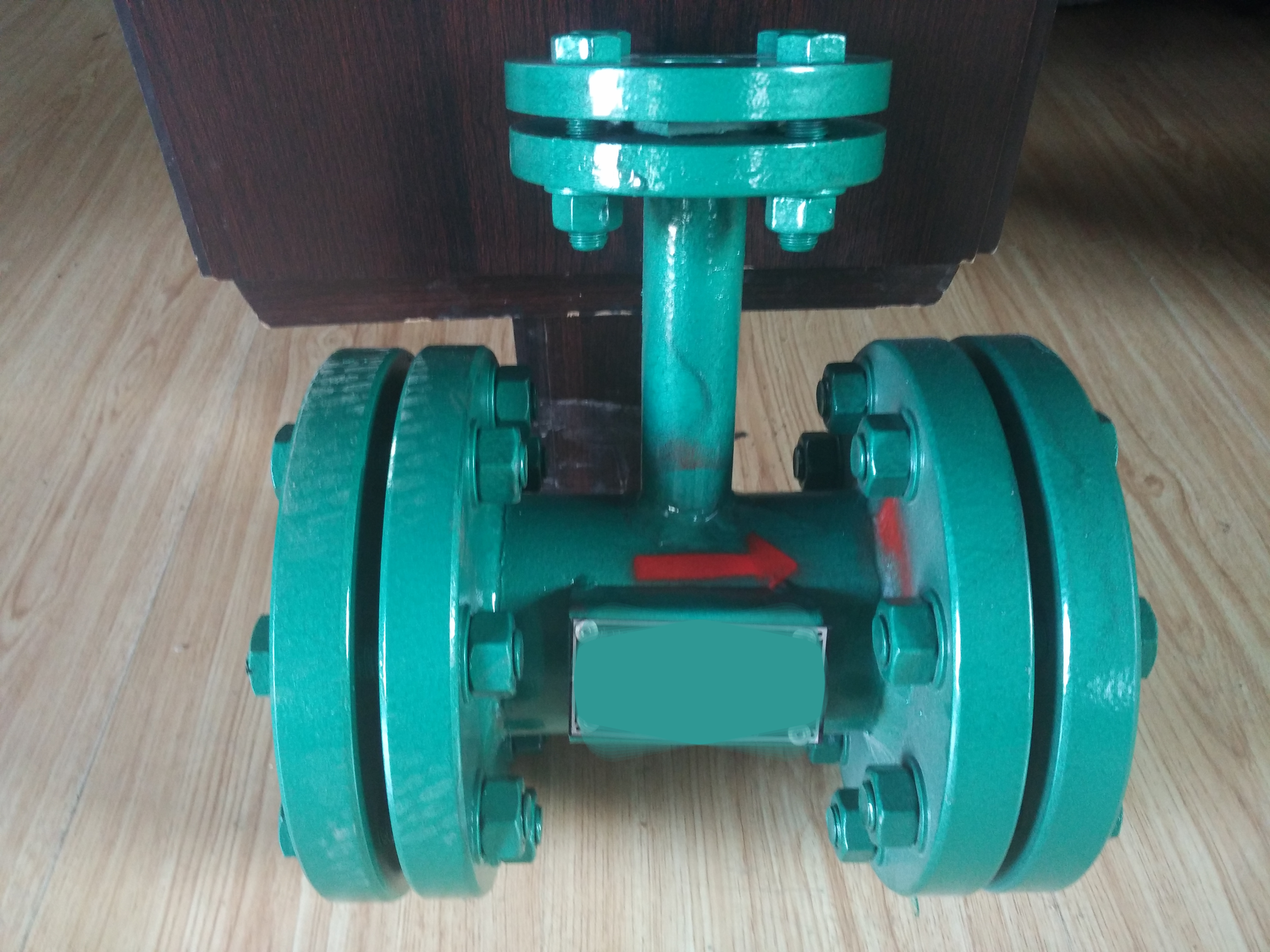
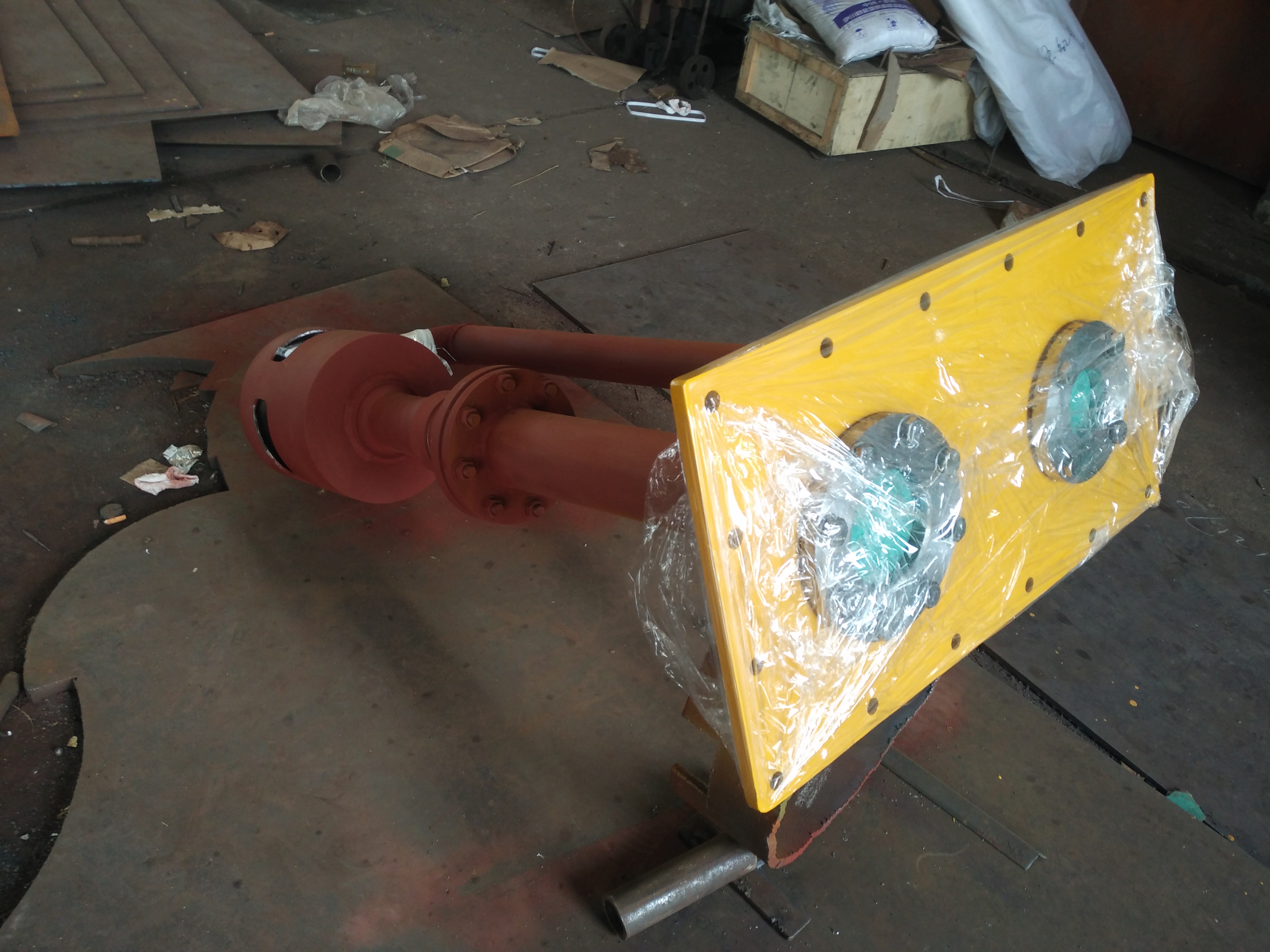
PZ type side mounted steam turbine spindle repair disc turning device:
The PZ type side mounted turbine main shaft repair disc rotation device is installed on the main shaft side, equipped with a large speed ratio swing pin wheel reducer, which meshes with the main shaft gear with a small gear to achieve continuous rotation of the main shaft at low speed. This device is small in size, lightweight, easy to install and use, flexible in adjustment, and versatile. It is a maintenance tool for steam turbine units.
Overview of maintenance and turning gear for the main shaft turning device of the steam turbine
The maintenance trolley is placed on the bearing seat between the low-pressure cylinder and the generator, and the transmission gear on the coupling between the low-pressure rotor and the generator rotor drives the turbine generator rotor to rotate at a speed of 3.35 r/min. The turning gear is composed of an electric motor drive wheel system, a reduction gear used to reduce speed, a meshing lever, and necessary interlocking devices.
1.1 Transmission gear system
The electric motor shaft drives the driving sprocket (37) to rotate, and drives the reduction gear through the chain, driven sprocket (36), worm (7), worm gear (XII), small gear of worm gear shaft (8), and idler gear (10). The reduction gear is connected to the turning gear shaft (VII) by a key, and the turning gear shaft meshes with the meshing gear (11) through the turning gear, which in turn meshes with the turning gear on the rotor.
1.2 Engaging lever
The meshing gear (11) can rotate on the gear shaft (14), which is installed on two swing plates (12) and (13), and the swing plate rotates with the turning gear shaft (VII) as the support shaft. The inner ends of these swing plates are connected to the control lever (18) using an appropriate connecting rod. Therefore, when the control lever (18) is moved to the "engaged" position, the meshing gear (11) will mesh with the large gear of the turning gear. When the speed of the turbine rotor increases enough to drive the turning gear, the meshing gear (11) will be in a passive state, and due to the torque of the transmission gear, the meshing gear (11) will automatically disengage from the meshing state. The bushings of the meshing gear, idler gear, and gear shaft, as well as the bushings between the turning gear shaft, turbine shaft, support, and main housing, are all sintered hole bronze and do not require lubrication. The worm bushing and the force surface on the worm are lubricated with pressure oil from the main bearing system through oil pipes.
2. Maintenance of the main shaft turning device of the steam turbine - Turning and repairing method
2.1 Leveling
Single rotor disc - measure the level of the upper frame, and only turn the machine after the upper frame level is qualified. When the turning data is unqualified, adjust the level by using the edge pad between the mirror plate and the force head (Buffalo Home, Muzuo, Yinping), and adjust the mirror plate power station (Zili) by grinding the snap ring. Buffalo Unit 1 is equipped with copper plates added between the power head and the mirror plate.
2.2 Measurement score-
During the turning of the Yinping Power Station, the upper guide, lower guide, shaft flange, and water guide are evenly divided into 8 points for measurement, with an angle of 45 degrees between the two points. A dial gauge is installed in the X and Y directions respectively, and the generator is rotated to record the readings of each point on the X and Y meters. The purpose of the data read by Tables X and Y is for checksum verification, where the data is aligned and does not use data from both tables at the same time. The purpose of a single generator disk is to adjust the verticality between the mirror plate and the shaft.
2.3 Unit Shafts - Measurement Methods
After the generator set is repaired and reinstalled, it needs to be connected to the shaft to determine the center of the unit. Axis measurement requires holding the upper guide pad and installing a dial indicator in the X and Y directions of the upper guide and water guide. Using a thousand pounds, measure the water guide or the upper end axis of the water guide in the X, X, Y, and Y directions. Calculate the total clearance of the water guide in the X and Y directions to obtain the center coordinate. [(+X)+(- X)]/2, [(+Y)+(- Y)]/2 Based on this calculation value, determine which direction the unit should move less in. The unit is determined by adjusting the upper guide vane, adjusting the anti screw of the upper guide vane to move the unit in the desired direction, and determining the adjustment amount through the dial indicator on the upper guide vane frame. After completing the adjustment, it is necessary to rotate the rotor several times to allow the rotor to fall freely before releasing the upper guide bearing to check the reading on the upper guide dial gauge to determine whether the shaft has been adjusted less and whether the required distance has been reached. Then tighten the upper guide pad again and set the dial gauge to -, measure the distance in the water guide distance+X, - X,+Y, - Y directions again, and adjust the above process until the distance in the+X, - X,+Y, - Y directions is equal or close, that is, the axis adjustment is completed.
2.4 During turning, turning data - any pattern
If the turning gear is stuck, it is possible that the thickness of the flange on the main shaft of the water turbine or generator is uneven, and there may be bending at the center after connecting the shaft, which is not on the same center. So it may cause the wheel and stop ring to get stuck, and the turning should be stopped in a timely manner, otherwise it may cause damage to the stop ring. In this situation, the flange should be treated, and the flange thickness should be treated evenly before connecting the shaft.
2.5 After the turning is completed, adjust the clearance between the upper and lower guide pads (pad clearance adjustment: after heating and coupling, turn the unit, and check the two gauges with each other, and connect - in the - X and - Y directions (when turning on the cathode, measure the turning data with - X and - Y deviation - X45 degrees, that is, 3- and 5- in the upper bracket). Start with any -, and record the turning data of X and Y gauges in the upper guide, lower guide, flange, and water guide, respectively, Make a table to calculate the total swing and net swing, and generate the swing curve. Analyze the net swing and adjust the tile clearance based on the net swing. Using CAD drawing methods, select a circle with a radius of 300 mm, and then create a circle with a diameter of 320 mm (determine the outer circle diameter based on the total clearance). The latter has a design clearance of 0.20 mm on one side (enlarge it by 100 times to create a circle). After production, observe the position where the swing curve appears, mainly in which direction, For example, if the center of the inner circle is at a deviation of 3-20 °, then move it in that direction by a certain degree. Then, measure the distance between the inner circle and the outer circle using the marking method, which is the clearance that needs to be adjusted. After the turning is completed, the rotor shall be lifted to clean the residual lard on the force pad. After the rotor is cleaned, the average stress of each force pad shall be adjusted. When the force is applied, the two hammers shall be used to adjust the lower anti screw of each force pad. When the force is applied, the water guide shall be installed in the X and Y directions respectively. When the force is applied, the dial indicator shall be set back to - (no force is applied on the anion pad and the wire runner is made in the runner room); Then start the unit center, and after the unit center is determined, weld and wire the impeller in the impeller chamber to ensure that the center is offset when the unit is reinstalled. The upper and lower guide coolers of the generator can be reinstalled. After the reinstallation is completed, the cooler should be kept under pressure, and the water guide part should be reinstalled, repaired, and sealed. The air enclosure should be tested for air tightness.
Reinstall the water machine and seal the water guide bearing. Complete all temperature sensor signals and add oil to the back cover cover of the upper guide test; Reinstall the lower guide bearing, check the temperature sensor of the lower guide, and reinstall the gear plate speed measuring device; Reinstall the relay fully closed and the travel switch above and below the no-load opening; Reinstall the mechanical overspeed device, check the micro switch signal of the guide vane position, the shear pin signal, and the high water level signal of the cover after adding oil to the lower and water guide vanes. Connect the oil supply pipeline of the relay, conduct pressure testing on the oil pressure device, check that all signals have been restored, and put the monitoring DI and DO modules into operation to verify the signals. Monitor and issue commands to monitor whether the enclosure, locking, and air brake are working properly, whether the technical water supply flow indicator is working properly, and fill the tail water with water. Check all parts of the water car room for water. Adjust the fully closed signal of the guide vane opening and correct the guide vane opening signal.
3. Analysis of the installation and operation of the turbine main shaft turning device maintenance and turning gear
(1) Regardless of the type of machine, the maintenance trolley should be installed as a whole on the split surface of the main shaft side- Install the base plate, fix it in the screw hole of the split bearing box with countersunk screws, and then fix the maintenance trolley on the base plate. At this time, the maintenance trolley gear should mesh well with the main shaft gear.
(2) The gear meshing position is required to be flush with the side where the gear exits. At this time, the gear shaft of the turning gear is located at the reducer.
(3) The forward and backward machine can maintain the axial displacement of the gear shaft of the turning gear, relying on the two types of screws at the rear end - out and in - to achieve shaft displacement. This machine is very convenient and safe, and is more convenient than the defects of the previous whole machine - pulling. It completely overcomes the strong physical labor and insufficient tightening of the fixing screws of the turning gear in the past, which caused the displacement of the turning gear.
(4) When turning, turbine oil should be poured into the bearing box to ensure that the bearing surface is fully wetted and to prevent dry friction.
(5) This machine can achieve continuous turning and turning through the control box. When turning, the force on the body of the disc is downward, that is, when viewed from the front of the car, the rotor rotates clockwise, and the disc is installed on the left side of the center.
-Special specifications can be arranged separately according to user needs for design schemes! Interested parties contact us!
Instructions for ordering the PZ type side mounted turbine spindle turning device for maintenance of the turbine spindle turning device:
Please complete the unmarked dimensions in the diagram of the distribution of turbine turning gear feet and the relationship between gears and feet (see Figure 2) and send it to our company for accurate and smooth installation and use of the turbine turning gear.
Steam turbine repair (turning), repair (turning), turbine main shaft rotation (device), steam turbine repair (turning) (device), repair (turning) (device), turbine (turning) (device), main shaft rotation (device)
The maintenance turning gear of the main shaft turning device of the steam turbine is shown in Figure 2
Basic parameters of PZ type side mounted turbine spindle repair disc turning device for maintenance of turbine spindle disc turning device:
盘车适应机组
盘车参数 | 10 万千瓦汽轮机组 | 12.5 万千瓦汽轮机组 | 20 万千瓦汽轮机组 | 30 万千瓦汽轮机组 | 其他机组 |
| 汽轮机盘转速度(转、分) | ≈ 1 | ≈ 1 | ≈ 1 | ≈ 1 | ≈ 1 |
| 盘车安装型式 | 旁置 | 旁置加辅助支撑 | 旁置 | 旁置 | 视具体情况 |
| 盘转方式 | 正、反转-动、连续 | 正、反转-动、连续 | 正、反转-动、连续 | 正、反转-动、连续 | 同左 |
| 减速机 | 型号 | XLD-63 | XLD-63 | XLD-63 | XLD-63 | 3322 | 视具体情况 |
| 输出速比 | 289 | 289 | 289 | 289 | 289 | 视具体情况 |
| 输出扭矩( N 、 M ) | 2200 | 2200 | 2200 | 2200 | 4600 | 视具体情况 |
| 电机 | 功率(千瓦) | 1.5 | 1.5 | 1.5 | 1.5 | 2.2 | 视具体情况 |
| 转速(转、分) | 1450 | 1450 | 1450 | 1450 | 1450 | 视具体情况 |
| 连接 | 节径( m ) | 180 | 180 | 110 | 1W | 215.9 ( S.5 —) | 视具体情况 |
| 模数(咖) | 6 | 10 | 6 | 6 | 12.7 ( D-2 ) | 视具体情况 |
| 电- | 380V 50HZ | 同左 | 同左 | 同左 | 同左 | 同左 |