time:2023-11-25 22:36:17Views:
The working status of the oil injector and main oil pump, the analysis of the reasons for the drop in the inlet oil pressure test of the main oil pump of a 200MW steam turbine, and the composition of the oil supply system of the 200MW steam turbine generally adopt a centrifugal main oil pump oil supply system with dual injectors. The entire system consists of a main oil pump, a high-pressure starting oil pump, an AC lubricating oil pump, a DC emergency oil pump, a dual oil injector (one for the main oil pump inlet and the other for the lubrication system), an oil cooler, an oil overflow valve, an oil tank, and some control valves.
The unit is powered by a high-pressure starting oil pump for the entire system during the static test of the regulating part during start-up and the impulse starting process. After the unit is set to speed, the main oil pumpprovides power oil to the system by switching the oil pump to ensure the normal operation of the unit. Due to the fact that the main oil pump adopts a centrifugal oil pump, although it is flat, its self suction capacity is poor, and it needs to be filled with oil at the inlet during normal operation. To meet this requirement, the first oil injector is used to supply oil to the main oil pump inlet, while the second oil injector is used to provide lubricating oil for the bearing lubrication needs. AC lubrication pump and DC accident pump are used to supply oil to the lubrication system in case of low lubrication oil pressure and accidents, to prevent oil interruption and tile burning, which may cause equipment damage.

The failure of the oil injector, as the oil pressure and quantity at the inlet of the main oil pump are provided by the injector, directly affects the oil pressure and quantity at the inlet of the main oil pump. Through multiple tests on oil injectors of different structures and sizes, it was found that the oil injectors have the following characteristics - (Ejector - Curve - as shown in Figure 2)
1. There is a critical flow rate -. When the outlet flow rate of the oil injector reaches the critical flow rate, the flow rate no longer increases and the outlet pressure of the oil injector drops sharply. In the timing of the nozzle size, the position of the critical flow rate is also determined. When the nozzle and throat diameter are timed, the position of the critical flow rate is also changed by changing the throat diameter.
2. The working oil pressure of the injector nozzle affects the injector. The change in oil pressure causes the injector to move up and down. When the working oil pressure is high and the outlet flow rate of the injector is the same, the outlet pressure head of the injector is also high.
3. Ejector - The distance between the nozzle and the throat of the diffuser is related. Small distance - the curve is steep, increasing the distance makes the curve flat.
Oil pump switching process - cause of oil pressure drop at the inlet of the main oil pump
According to the design, when the unit speed reaches 2 950r/min, the high-pressure starting oil pump and main oil pump can automatically start working and undertake the oil supply task. At the same time, the starting oil pump can smoothly exit the no-load operation state. After a constant speed of 3000 r/min, the control room will operate the switch to stop and start the oil pump - now it will automatically switch.
Through the start-up and operation of several power plants, although the pressure head of the main oil pump has been higher than that of the starting oil pump after the unit was set at a constant speed of 3000 r/min, and the automatic switching conditions have been met, from the working state of the starting oil pump, it is not in an unloaded state, that is, the main oil pump has not been put into operation to supply oil to the system. This is mainly caused by the non opening of the check valve at the outlet of the main oil pump. The check valve can only be opened when the outlet pressure head of the main oil pump is higher than the starting oil pump pressure head and there is a certain pressure difference, allowing the main oil pump to supply oil. In this way, the only way to switch the oil pump is to close the cut-off valve at the outlet of the starting oil pump and reduce the pressure head.
Below, we will analyze the reason for the decrease in oil pressure at the inlet of the main oil pump during the pump cutting process through the check valve structure and oil injector.
The interface structure of the main oil pump outlet check valve is shown in Figure 3.
The area ratio of both sides of the check valve is 1502/1202=1.562 5
When the outlet pressure pz of the main oil pump is greater than 1.562 5pq (opening pressure), the check valve can be opened, and the main oil pump can supply oil to the system. Assuming pz=20kgf/cm2, the power oil pressure PD - must be reduced from 20kgf/cm2 at startup to PD=20/1.562 5=12.8kgf/cm2 before the check valve at the outlet of the main oil pump can be opened. The main oil pump and the high-pressure starting oil pump run in parallel to supply oil to the system. After the main oil pump is in normal operation, it returns to PD=20kgf/cm2. At this point, it is possible to determine whether it is in a no-load state by observing the starting oil pump current.
Due to the fact that the inlet oil pressure and oil volume of the main oil pump are provided by the No.1 oil injector, the fluctuation of the inlet oil pressure of the main oil pump is directly related to the outlet pressure head of the injector. Below is an analysis of the pump cutting process - the working state of the oil injector.
After the unit is at a fixed speed, the pressure head of the main oil pump has been established. Assuming that the outlet check valve of the main oil pump is open at this time, the main oil pump and the high-pressure starting oil pump operate in parallel to supply oil to the system, and the oil injector works at A - (see Figure 4). If the oil pump is stopped and started, the main oil pump supplies a large amount of oil to the system. In order to meet the needs of the main oil pump, the outlet flow rate of the injector also increases, and the pressure head of the injector outlet drops to positive working B, which leads to the automatic switching process. From this process, it can be seen that the inlet oil pressure of the main oil pump will also decrease, but it will only decrease to the designed normal operating range, and will not continue to decrease.
However, after the unit was set to speed, the pressure head at the outlet of the main oil pump had been established, and the check valve at the outlet of the main oil pump had not been opened. The oil injector was working at C -, and only a portion of the oil Q2 was discharged by starting the oil discharge valve. From the above analysis of the check valve, it is only related to the cut-off valve at the outlet of the starting oil pump, which causes a decrease in power oil pressure. When the pressure drops to pz/1.562 5, the check valve opens. During the descent process of PD, the outlet pressure head of the oil injector also decreases from C to D - (Figure 4). After the check valve is opened, the main oil pump and the starting oil pump supply oil to the system at the same time. Because the outlet pressure of the starting oil pump is low at this time, most of the oil is provided by the main oil pump. Therefore, the outlet pressure head of the oil injector decreases from D to E -. At this time, the oil pump stops, and the oil volume of the main oil pump increases. The outlet pressure head of the oil injector continues to decrease from E to F -. When the main oil pump works normally, PD recovery oil injector - move upwards, and the outlet pressure head rises to reach positive working B.
From the above analysis, it can be seen that during the oil pump switching process, the oil injector always operates within the normal working range, and the outlet flow rate has not reached the critical flow rate. Therefore, the decrease in the inlet oil pressure of the main oil pump is mainly due to the area ratio of the check valve. When switching the oil pump, it is necessary to reduce the power oil pressure and cause it to rise. The magnitude of the decrease mainly depends on the magnitude of the change in power oil pressure, and even due to improper operation, when the check valve is not opened and the starting oil pump is not exited, the starting oil pump is stopped. This can cause a sudden drop in power oil pressure and a drastic change in the outlet pressure of the oil injector, resulting in a drop in the main oil pump pressure and adverse consequences.
-Reasons for oil pressure drop at the inlet of the main oil pump under non normal working conditions such as speed inspection and tripping
1. Analysis of working conditions- During the speed verification process, as the unit speed increases, the main oil pump speed also increases. According to the centrifugal pump, the outlet pressure head also increases, resulting in an increase in the oil consumption of the adjustment system and the oil consumption of the 1st and 2nd injectors. This requires the main oil pump to supply a large amount of oil to the 1st injector. As can be seen from the oil injector, when the oil injector is in operation, the critical flow position is fixed. Therefore, when the main oil pump requires a large amount of oil, due to the small margin of the oil injector (from positive working oil to critical flow), it may cause the outlet pressure head of the oil injector to drop when the oil injector operates in a critical state, which is reflected at the inlet of the main oil pump, and the oil pressure drop is -.
2. Braking situation. Since the opening of the oil discharge port is at the designed empty load position when the regulating assembly is at 3000 r/min, and the regulating assembly is at the instantaneous oil discharge port when it is opened to a large value after the tripping, the instantaneous regulating oil volume sharply increases, the return oil of the hydraulic servo motor cannot return to the inlet of the main oil pump in time, and all the required flow is provided by the oil ejector, so that the No. 1 oil ejector is at the critical flow working state, and the oil pressure at the inlet of the main oil pump drops.
Methods and suggestions for oil pressure drop in the main oil pump population
1. Modify the check valve at the outlet of the main oil pump to reduce its area ratio, from surface contact to contact, so that it can automatically switch to the oil pump.
The check valve has now been modified, Φ 150mm diameter changed to Φ 120+(4-5) mm, but if the oil pressure of the starting oil pump is high and does not match the main oil pump, it cannot automatically switch. This requires the operating personnel to close the outlet cut-off valve of the starting oil pump, pay attention to observing whether the starting current drops to determine whether the starting oil pump is in a light load or no-load operation state, and then stop the starting oil pump.
2. Improve the oil injector to make it flat and ensure that the critical flow rate meets the needs of non normal working conditions such as speed testing and tripping.
When designing an oil injector, the outlet flow rate and outlet pressure head of the injector are both selected for positive working hours, which may result in a small margin for the injector.
By retrofitting several power plant oil injectors and increasing the throat size of the injectors, the critical flow rate of the injectors can be increased. This can also be analyzed through the approximate calculation of the oil injector in reference 1:
According to reference [1]:
Pressure head ratio m=h1/h2
The relationship between pressure head ratio and injection coefficient q:
M=(1+q) 2 (1/ ξ*α 0) 2
Relationship between throat area and ejection coefficient:
F1/F0=(1+q) 2
Equation - h1- nozzle working oil pressure head
H2- Ejector outlet pressure head
ξ—— Expansion tube working coefficient
α 0- nozzle flow coefficient
F1- Expansion pipe throat area
F0- nozzle outlet area
From the above relationship, it can be seen that as F1 increases, q also increases, that is, under the same nozzle diameter, the outlet flow rate of the injector also increases. As F1 increases, m also increases. Under the same working oil pressure, the outlet pressure head h2 of the injector decreases- Increasing F1 in terms of quality means selecting the outlet flow rate and outlet pressure head of the oil injector not at the designed positive working position, but at the working position where the unit requires a large amount of oil in non positive working conditions and the inlet oil pressure of the main oil pump is higher than the saturated steam pressure of the turbine oil by 0.34kgf/cm2. This can ensure that the main oil pump is not subjected to cavitation under special working conditions and operates safely and reliably.
According to references [1] and [2], as well as the on-site modification of the oil injector, it is believed that the throat distance of the oil injector should be selected as 1.8 times the throat diameter, and the oil injector should be flat, with strong adaptability to the main oil pump.
3. It is recommended to make a curve of the oil injector and determine the position of the critical flow rate during the oil injector test, so as to determine whether the oil injector can meet the requirements of different operating conditions of the unit.
This information was collected online and published by Ying, Qi Xiaofeng, Che Limin, and Wei Wei.
The steam seal heater adopts a horizontal U-shaped surface heat exchan...

The steam seal cooler generally adopts a horizontal U-shaped surface h...
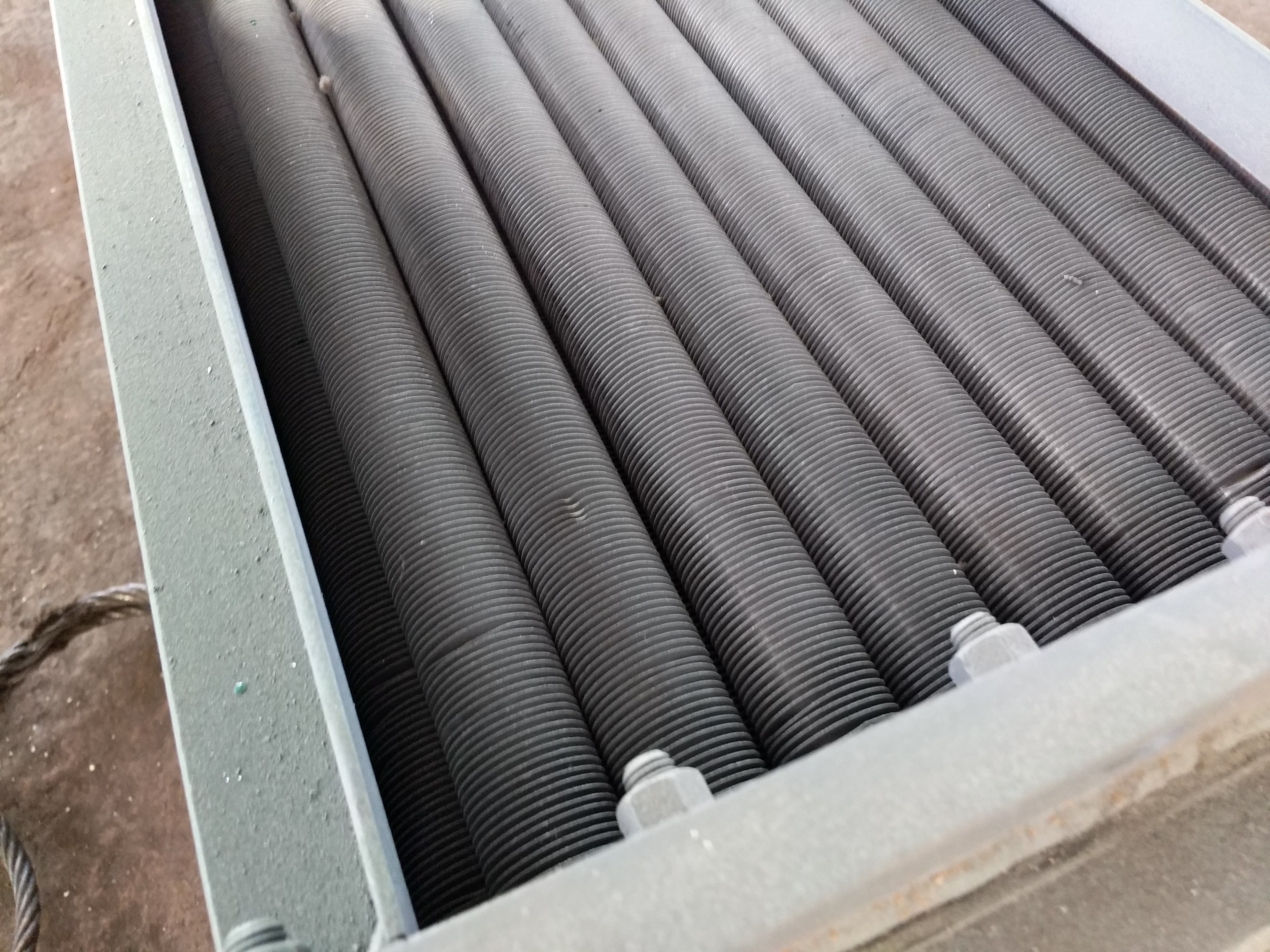
The air cooler adopts finned tube material, single metal finned tube a...
The waste heat recovery device, also known as the energy collector and...
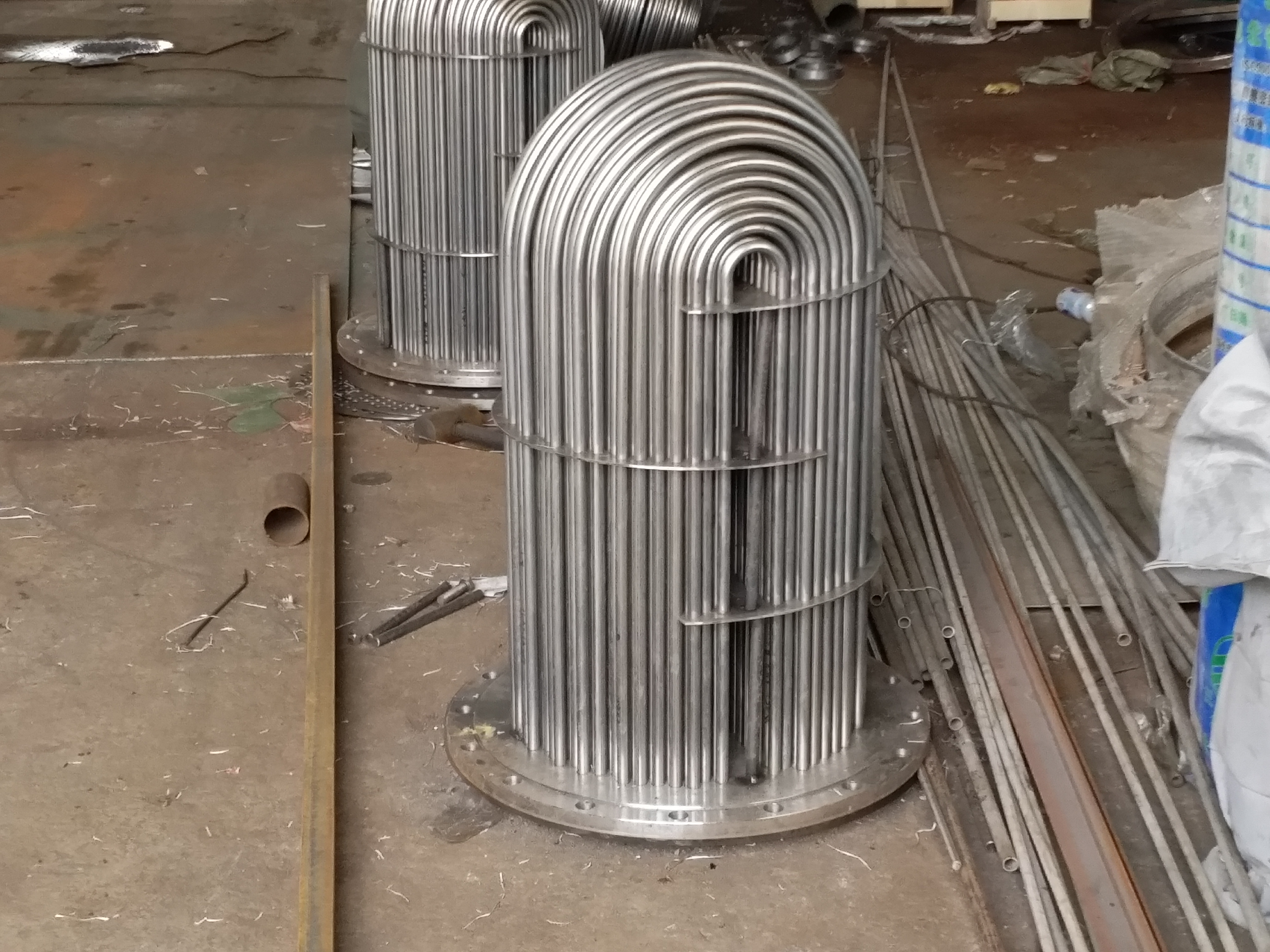
The U-shaped tube is used as a cooling tube for heat exchange tubes, a...

Overview of condenser tube replacement and condenser stainless steel t...
Welded steel pipes (also known as slotted pipes and welded pipes) are ...
Welded steel pipes (also known as slotted pipes and welded pipes) are ...
Manufacturer of shaft seal heaters, also undertaking pipe replacement ...
Welded steel pipes (also known as slotted pipes and welded pipes) are ...
Steam turbine oil-water cooler pipe replacement, marine oil-water cool...
When purchasing a column type oil cooler for tube and core replacement...
The automatic steam liquid two-phase flow steam trap, also known as th...

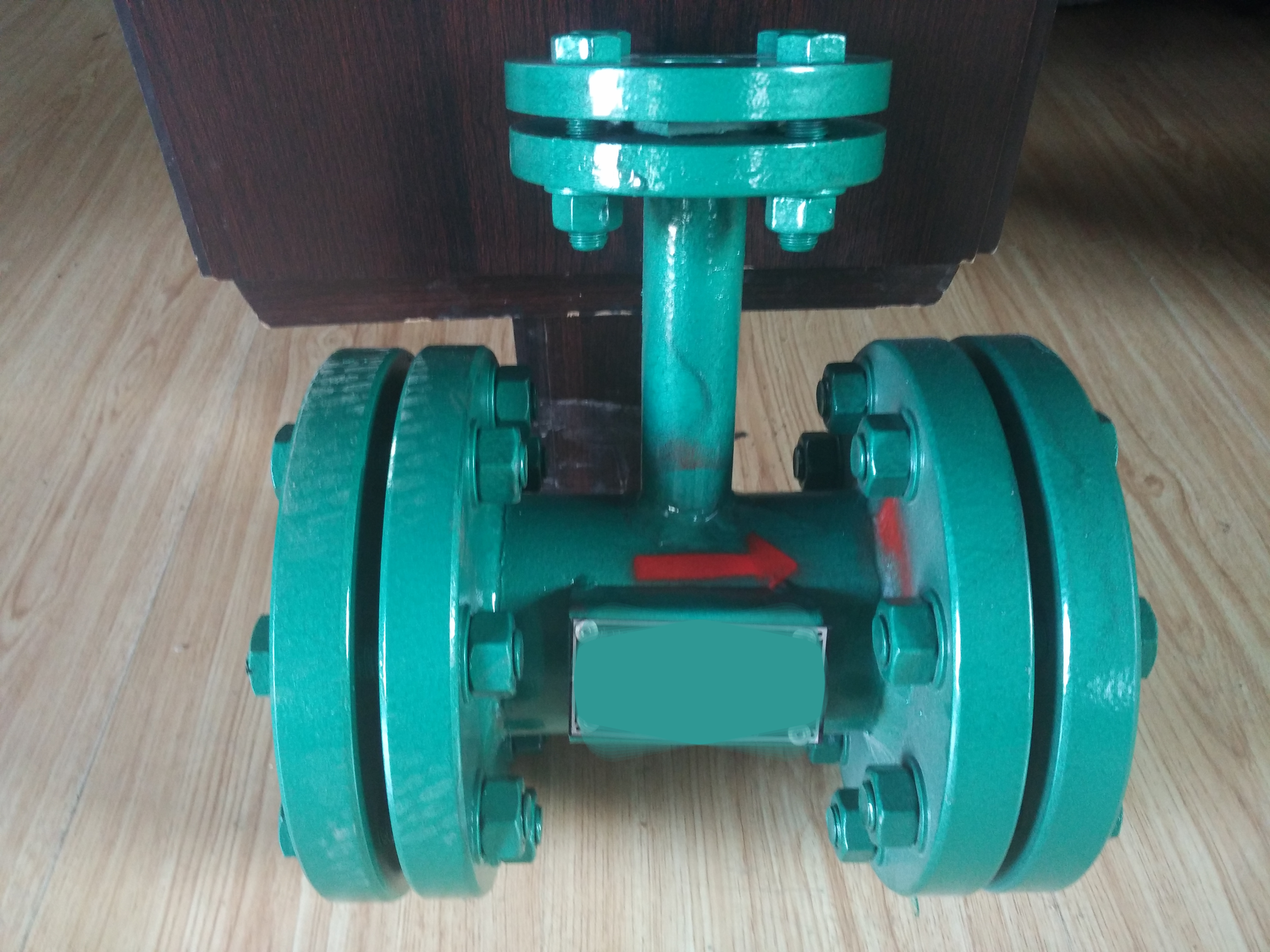
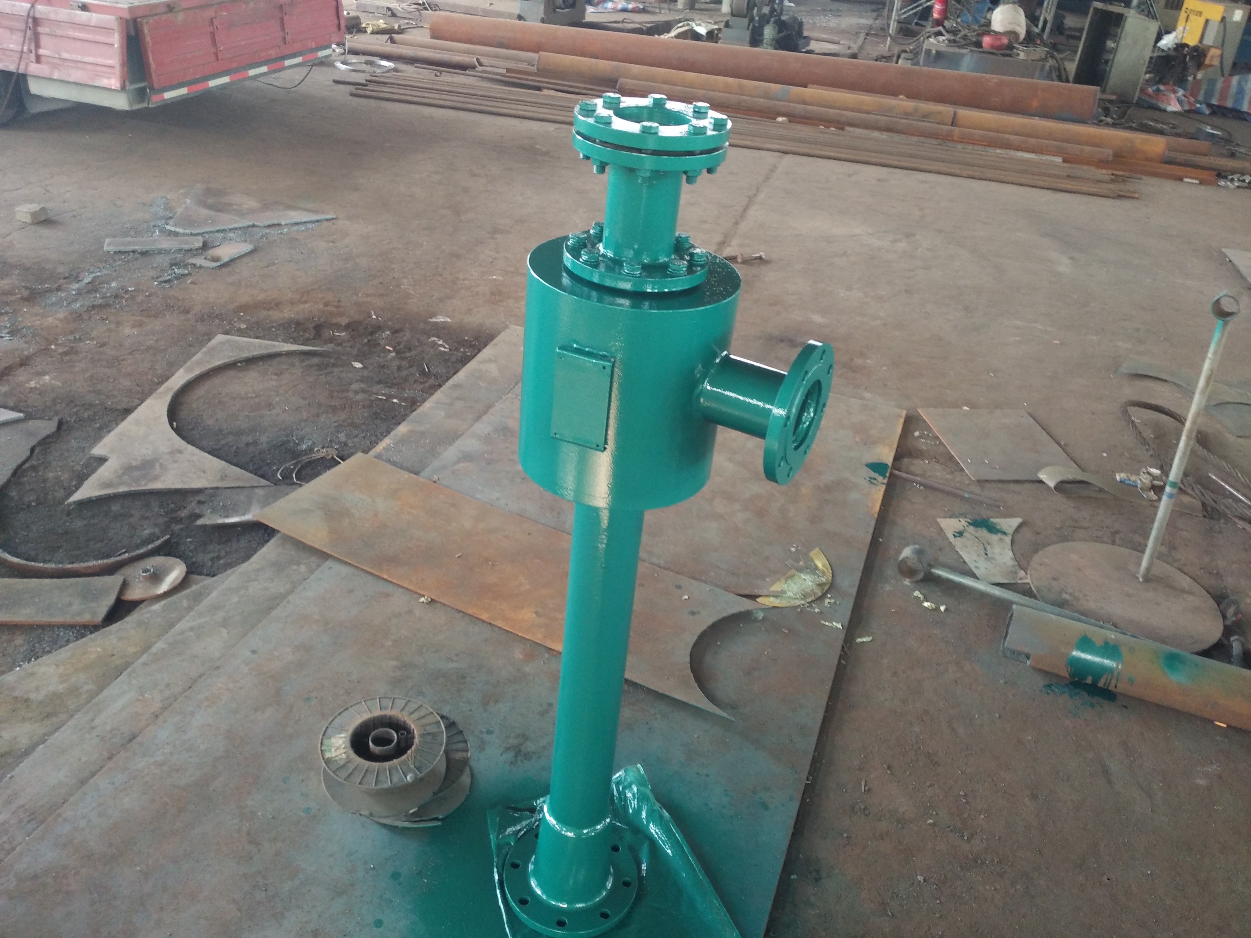
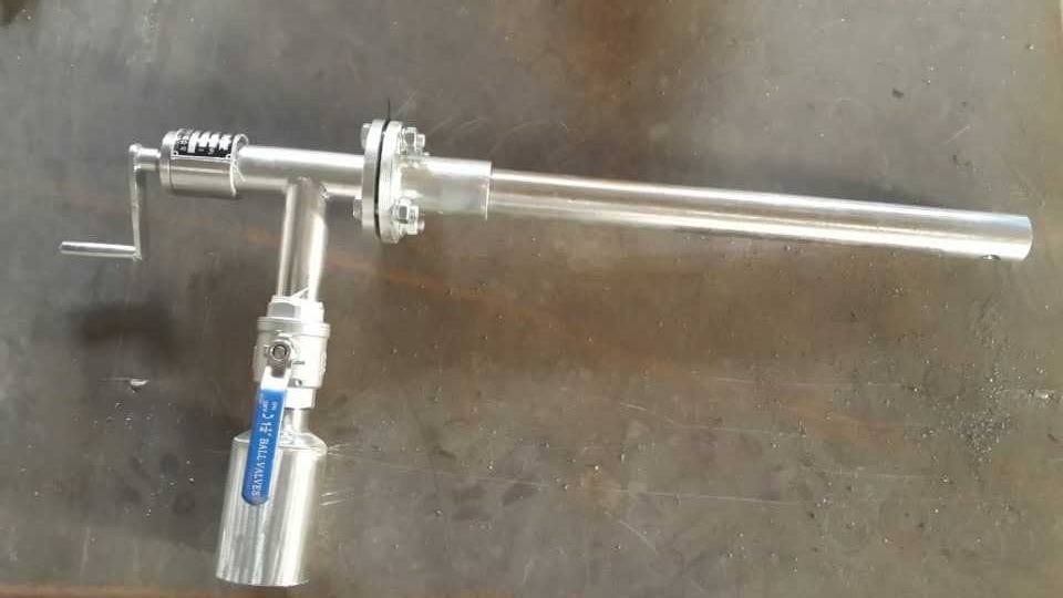
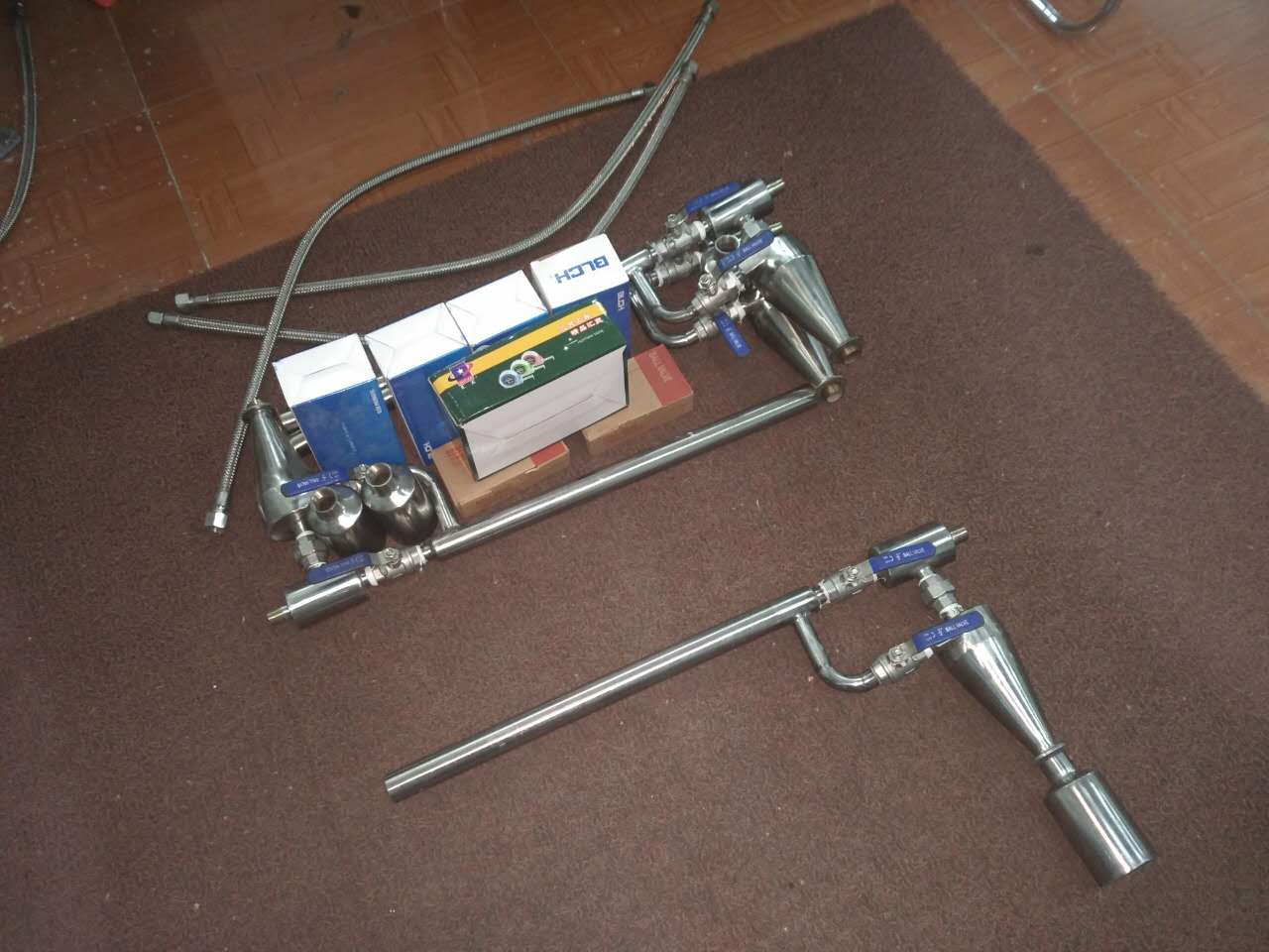
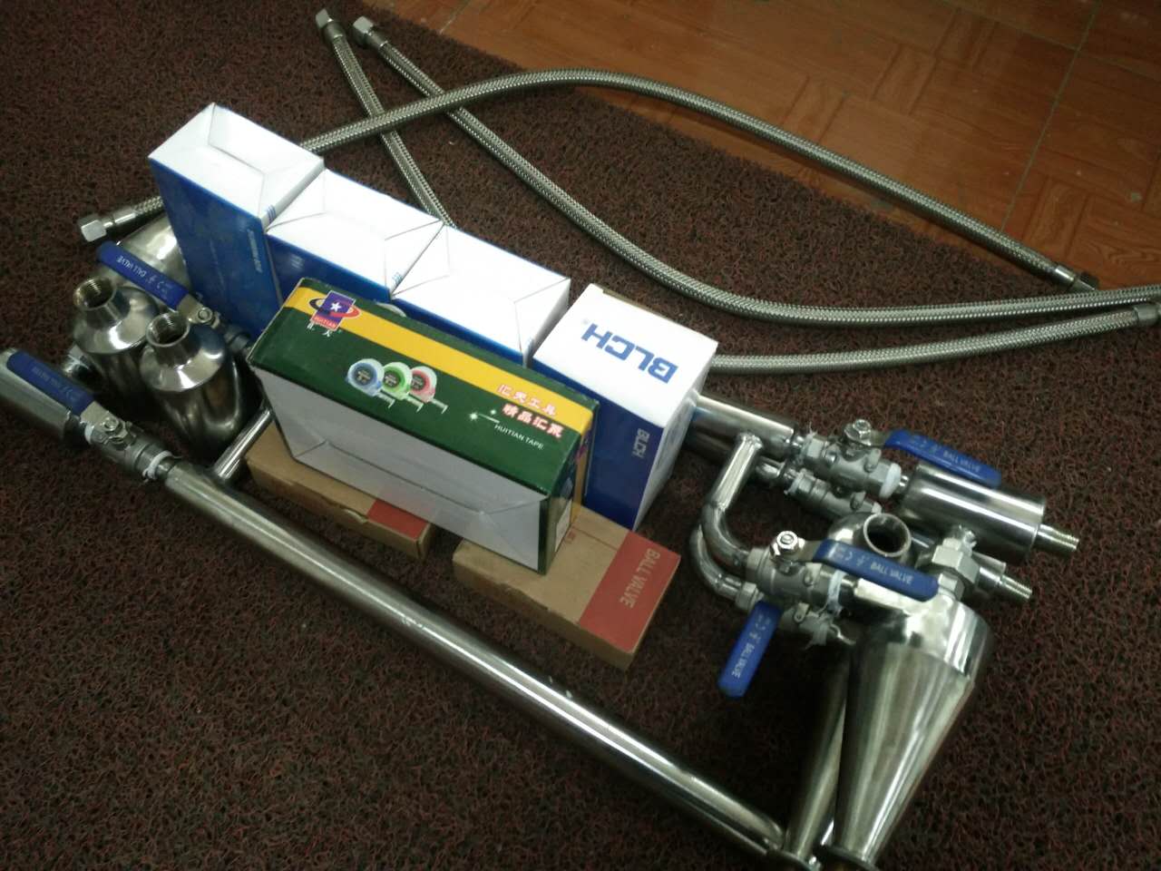
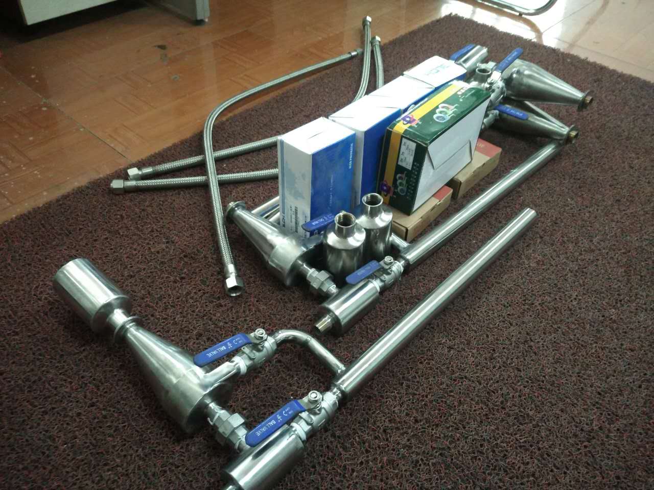
The oil injectors produced by Lianyungang Lingdong Electromechanical E...
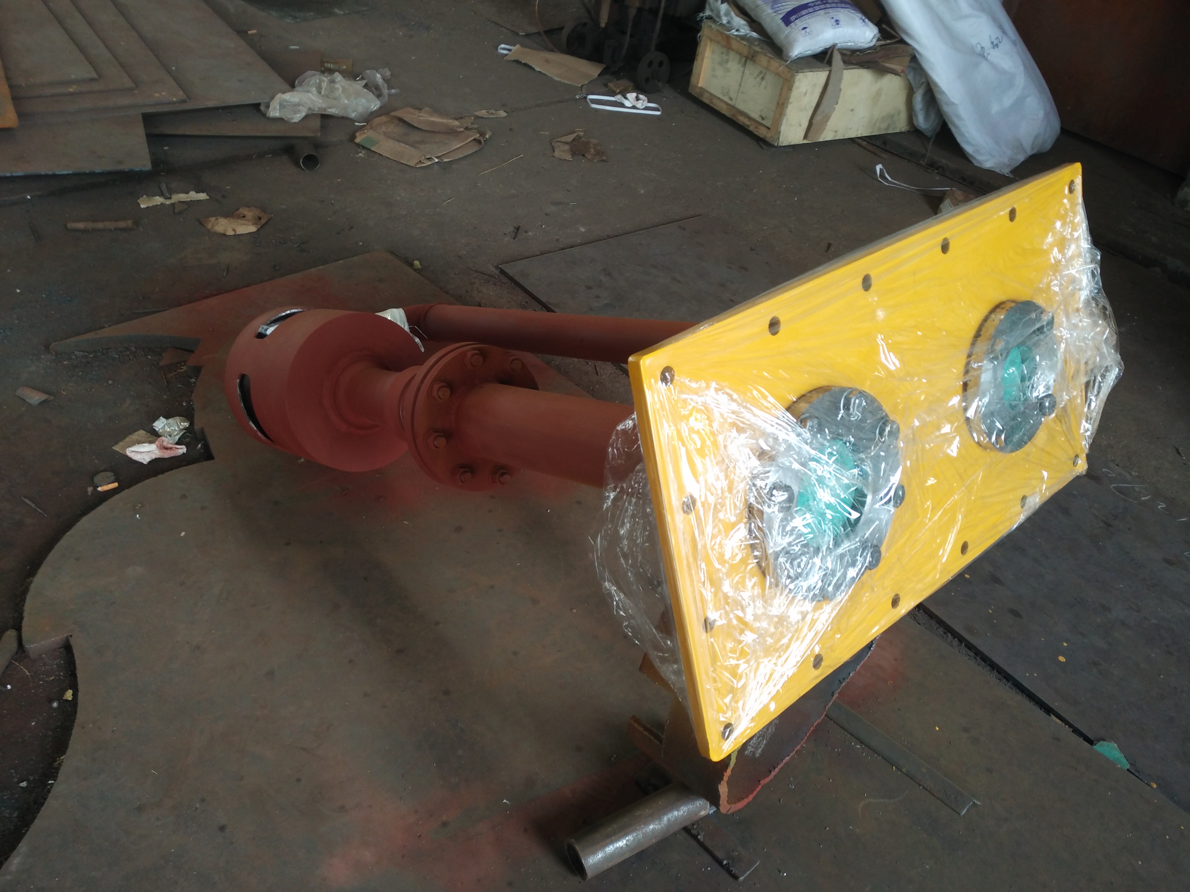
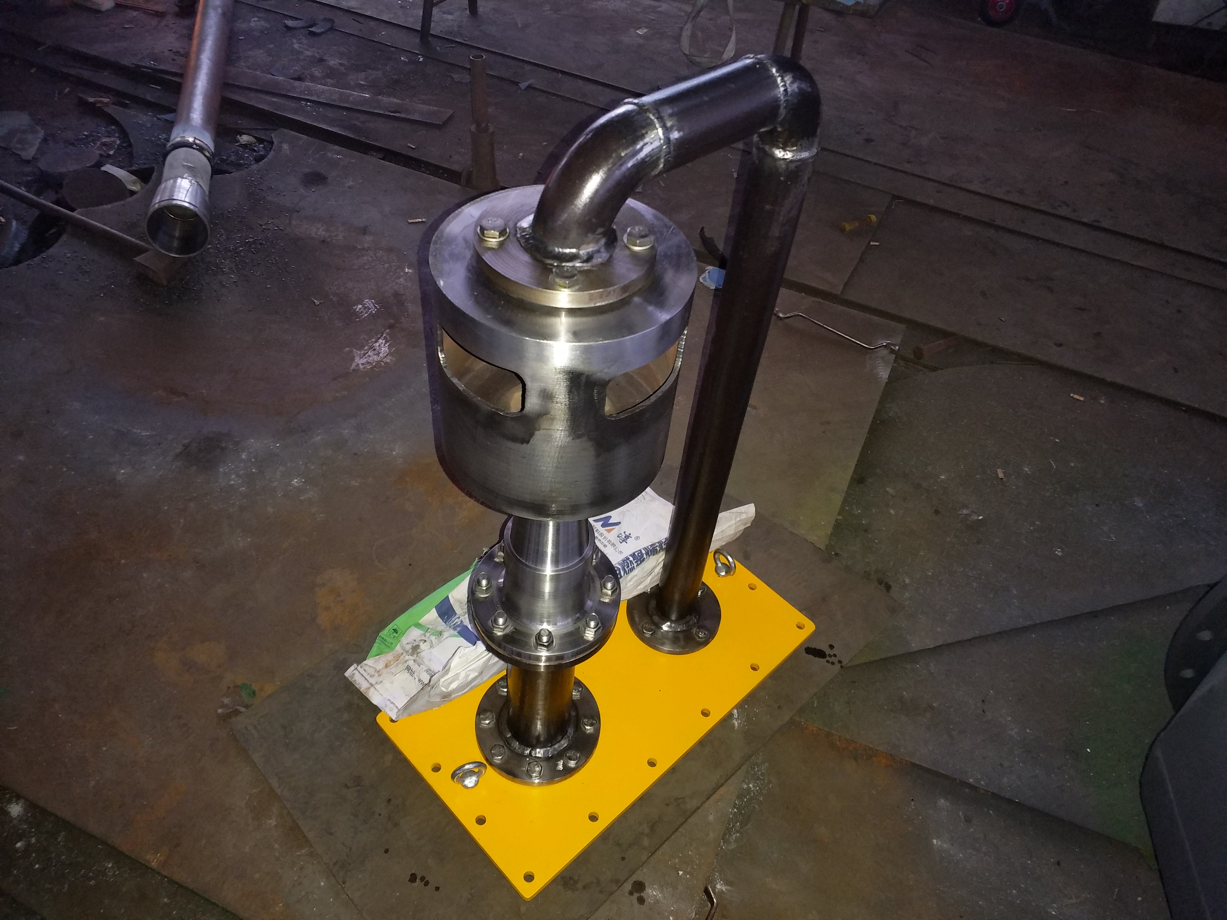
The oil injector is composed of a nozzle, a filter screen, an expansio...
A steam injector is a device that is powered by steam and is needed in...

Calculation of cooling area of sampling cooler 1: If the sample flow r...
The sampling of fly ash sampler is selected on the flue between the ou...
The use of carbon steel material in coal powder samplers has caused ma...
The working status of the oil injector and main oil pump, the analysis...

The oil supply and lubrication oil injectors are completely identical ...
The installation and operation of the coal powder sampler and mobile c...
The manual mobile coal powder sampler produced and manufactured by Lia...
The oil injector of Lianyungang Lingdong Electromechanical Equipment C...

Keep up on our always evolving product features and technology. Enter your e-mail and subscribe to our newsletter.
Copyright © 2012-2026 00LD连云港灵动机电设备有限公司遥遥制造汽液两相流液位自动疏水调节器、汽液两相流液位控制器、汽液两相流疏水器及油雾分离器、排油烟装置,可提供除氧器以及凝汽器换管改造、冷油器现场更换管束增容服务。 00ld.com 版权所有


