time:2023-11-25 22:55:57Views:
-Purpose of steam trap
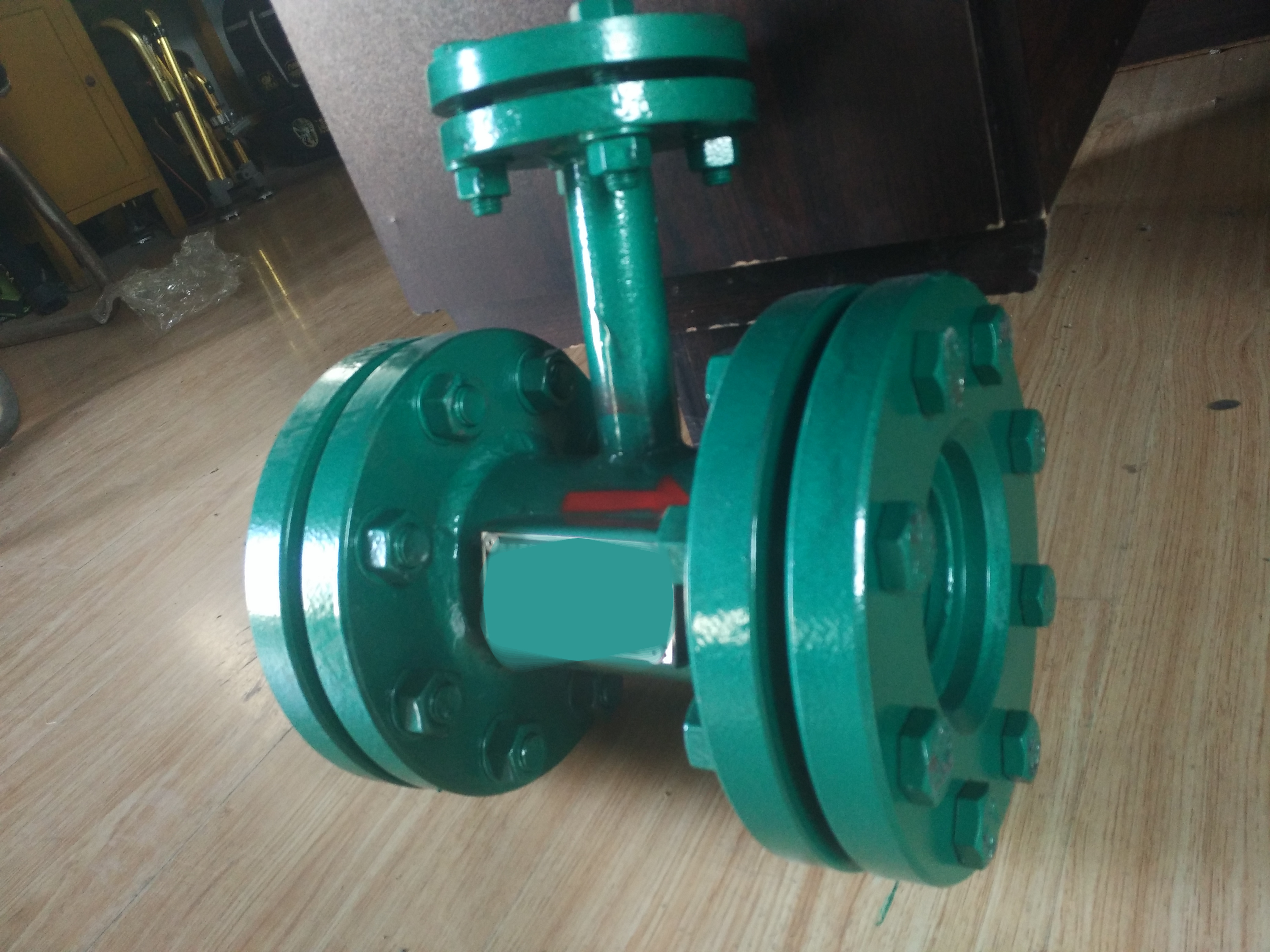
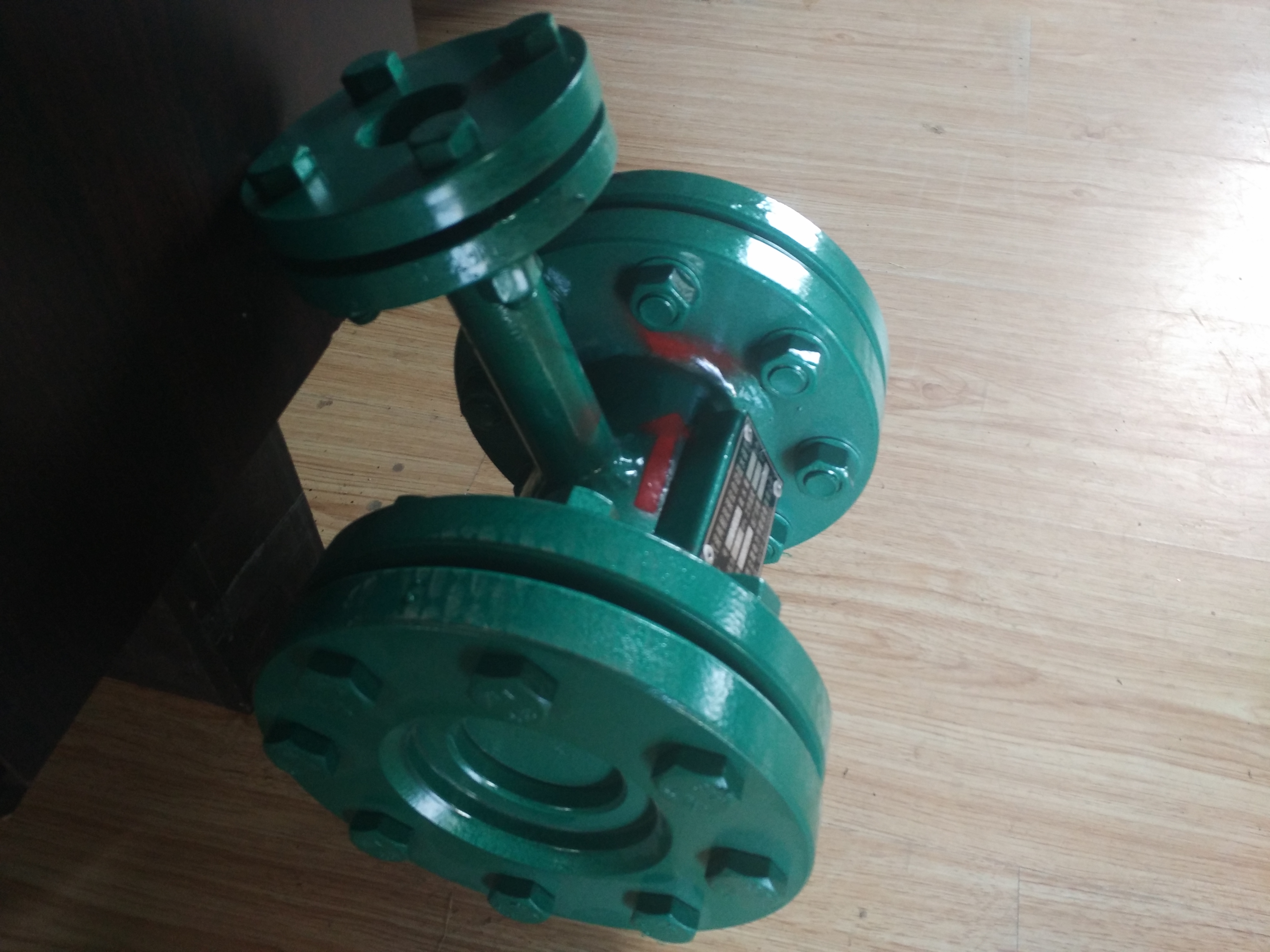
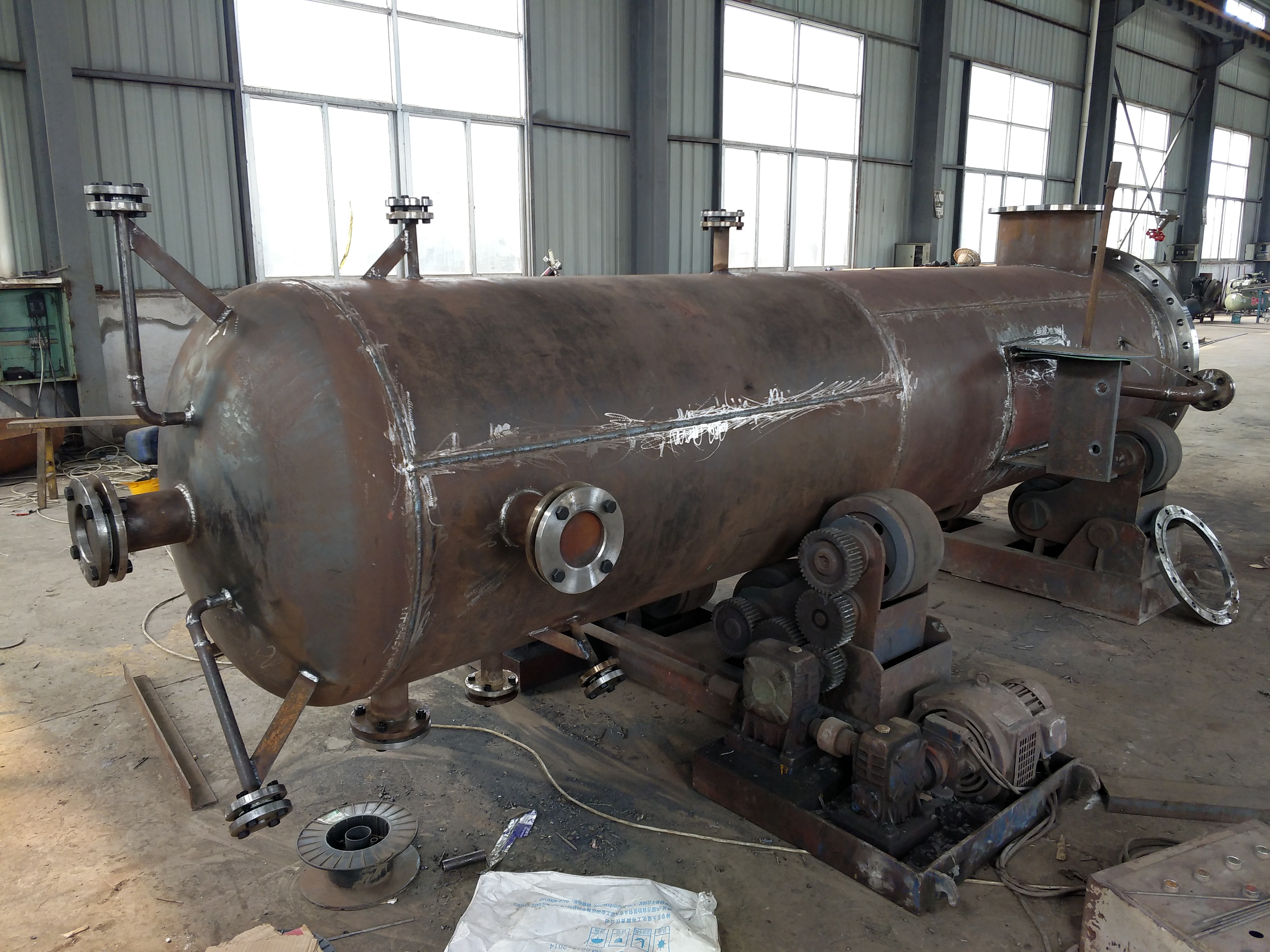
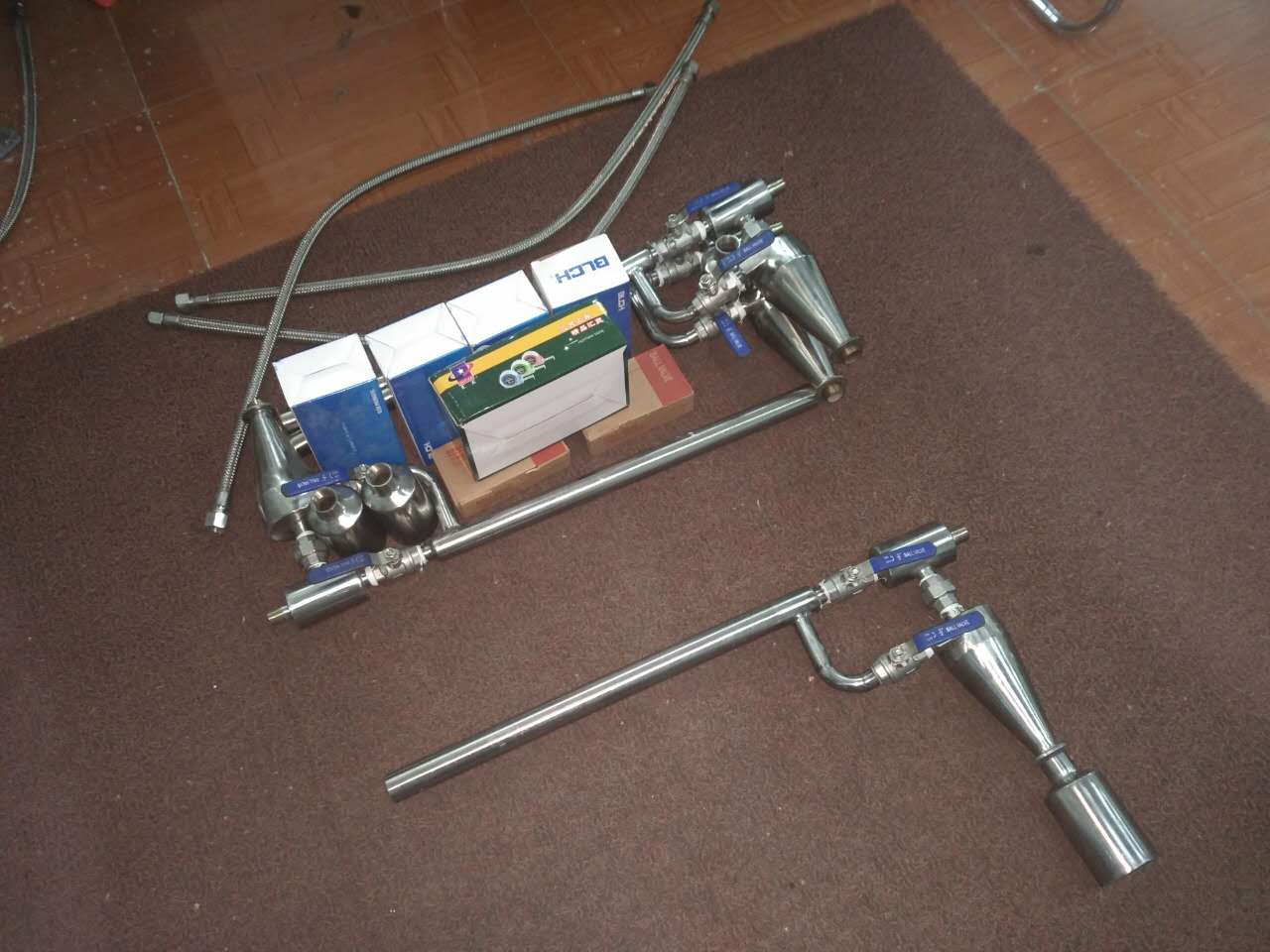
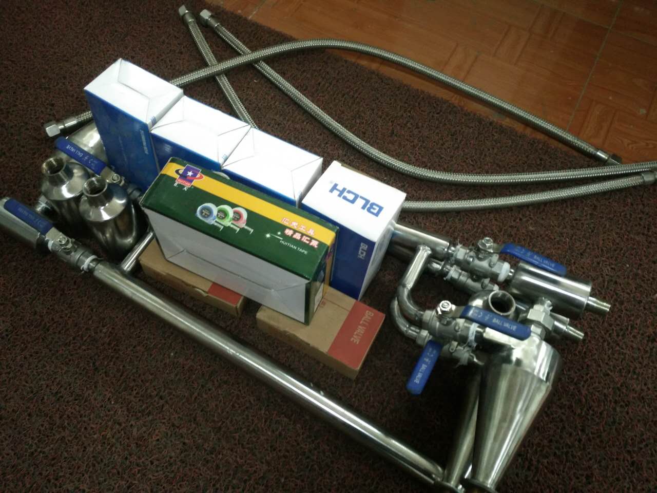
The automatic steam liquid two-phase flow steam trap, also known as the gas-liquid two-phase flow control valve, is suitable for the water level self operated intelligent control of pressure vessels such as high and low pressure heaters, continuous discharge expansion vessels, raw water heaters, and heating network heaters in the power industry. The steam liquid two-phase flow drain valve is an alternative to electric valves and floating balls.
After the customer installed the steam liquid two-phase flow automatic drain valve as a type of water level controller, the on-site repair and operation maintenance workload significantly decreased, saving repair costs and reducing labor intensity. Significantly improved the operational management level of the equipment. Users refer to it as maintenance equipment.

2、 Steam trap--
1. The automatic steam liquid two-phase flow trap belongs to self operated intelligent regulation, with sensitive and accurate liquid level adjustment.
2. Non power consuming, mechanical moving parts, requiring repair, valve core made of high-quality stainless steel for corrosion resistance, long.
3. Without pneumatic and electric thermal control systems and complex thermal auxiliary equipment, it is called maintenance equipment.
4. The system is simple, easy to install, and requires electrical control, pneumatic, etc.
5. High pressure and high temperature have an impact on regulation energy.
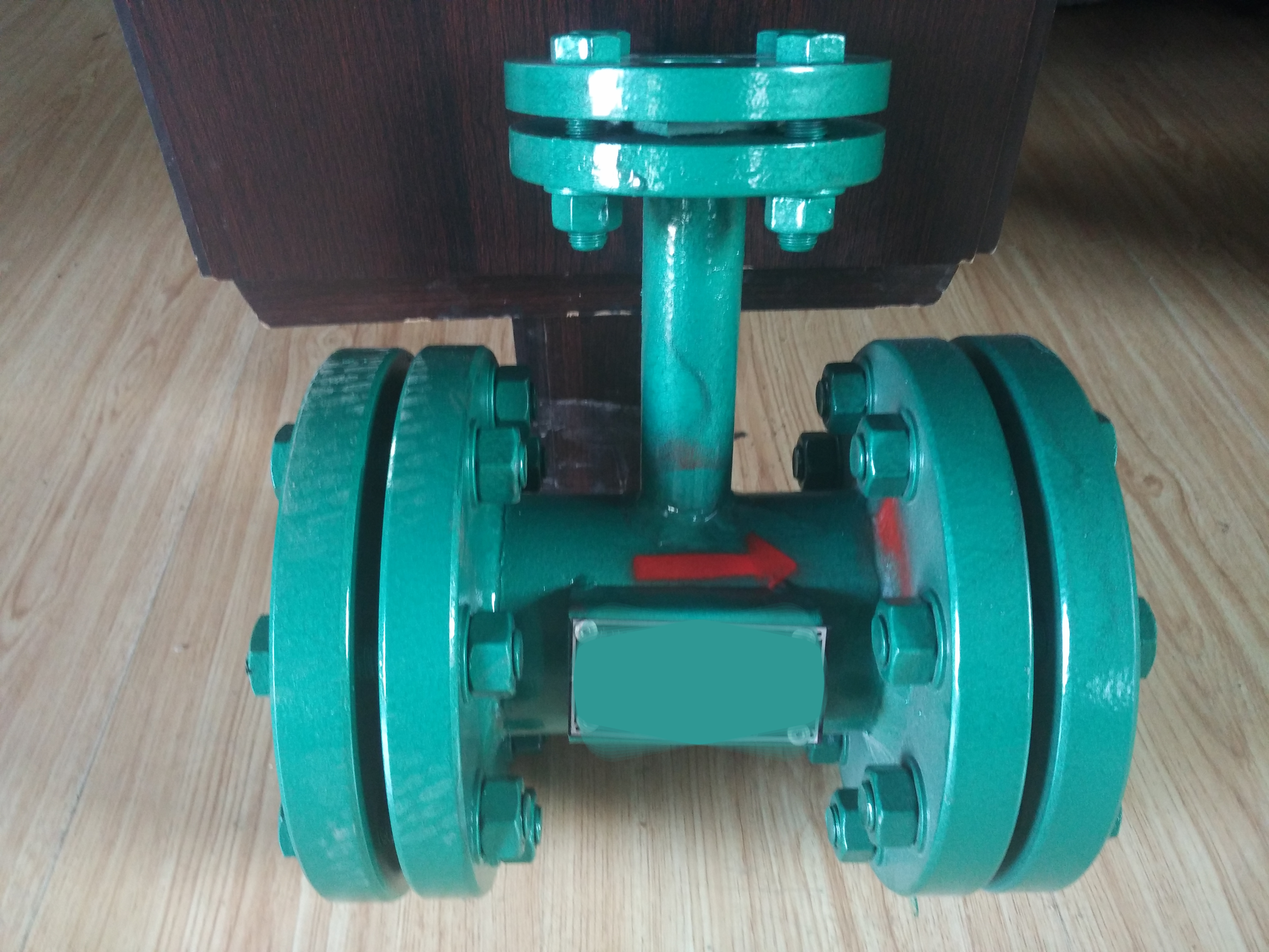
3、 Working principle of drain valve
The self regulating liquid level controller for gas-liquid two-phase flow is a comprehensive concept liquid level controller designed based on fluid mechanics theory and control principles, utilizing the flow of gas-liquid two-phase flow. It belongs to self operated intelligent regulation and relies on the increase or decrease of steam volume in the container as the driving force of the machine. The connection system of the controller on the container of the thermal power plant is shown in the figure. The function of a regulator is to control the outlet water volume, which is equivalent to an electric machine in an automatic regulation system. The regulation principle is that when the water level of the container rises, the amount of steam coming from the upper part decreases, resulting in a decrease in the amount of steam sent to the regulator. As a result, the amount of steam flowing through the regulator two-phase flow decreases, the amount of water increases, and the water level of the container decreases accordingly. On the contrary, when the water level decreases, the amount of steam from the upper part increases, resulting in an increase in steam flow through the regulator and a decrease in water flow, and the water level of the container rises accordingly. Thus, the self regulating control of the container water level has been achieved.
4、 Instructions for ordering drain valves
1. What equipment does the user provide for the matching gas-liquid two-phase flow device, as well as parameters such as pressure, temperature, and outlet pipe diameter.
2. Provide various connection systems - flanges, with sizes for connecting pipes.
3. Valve core selection (divided into carbon steel and stainless steel).
5、 Specification and model of liquid level controller
Specification, model, connecting diameter, suitable for the material of the valve core of the unit
ZTQ-50 DN50 304 below 100MW
ZTQ-80 DN80 below 100MW
ZTQ-100 DN100 below 100MW
ZTQ-125 DN125 100MW-200MW
ZTQ-150 DN150 100MW-200MW
ZTQ-200 DN200 300MW
ZTQ-250 DN250 300MW
In this case, the functions of low consumption and high efficiency automatic steam traps include the following three aspects:
(1) Exclude air and other non condensable gases
(2) Prevent steam leakage.
(3) Can quickly eliminate the generated condensed water.
Low consumption, high - function of automatic steam trap: Simply put, it is an automatic valve that drains and blocks steam. When steam becomes condensate, the temperature also decreases, and the heating element of the steam trap contracts. The needle valve is opened to discharge the condensate. During this process, with the activity of the condensate, the steam is inevitably carried out, but the steam heats the heating element of the steam trap, causing it to expand and seal the valve. The position of this heating element can be adjusted. When the exhaust volume of the steam trap is too large, the position can be tightened, and vice versa, the position can be loosened. The basic function of a low consumption and high efficiency automatic steam trap is to completely discharge condensed water, air, and carbon dioxide gas from the steam system; Simultaneously - automatically prevent steam leakage to the greatest extent possible. This may sound simple, but there are many factors that can affect the performance of steam traps during operation, such as selection, installation, and use. The function of a steam trap is to use only steam on equipment that utilizes steam. In this type of equipment, condensed water must be generated, which becomes a harmful fluid and also contains air and other non condensable gases, becoming the cause of equipment failure and reduced functionality.
Low consumption high - automatic steam trap can automatically identify steam and water (excluding thermal static type), thereby achieving the purpose of automatic steam blocking and drainage- Applied in industries such as petrochemicals, food, and power plants, it plays a significant role in energy conservation and emission reduction.
Self regulating liquid level controller for gas-liquid two-phase flow
-Purpose and application of self regulating water level controller for gas-liquid two-phase flow--
The self regulating liquid level controller for gas-liquid two-phase flow is suitable for intelligent water level control of pressure vessels such as high and low pressure heaters, continuous discharge expansion vessels, raw water heaters, and heating network heaters in the power industry.
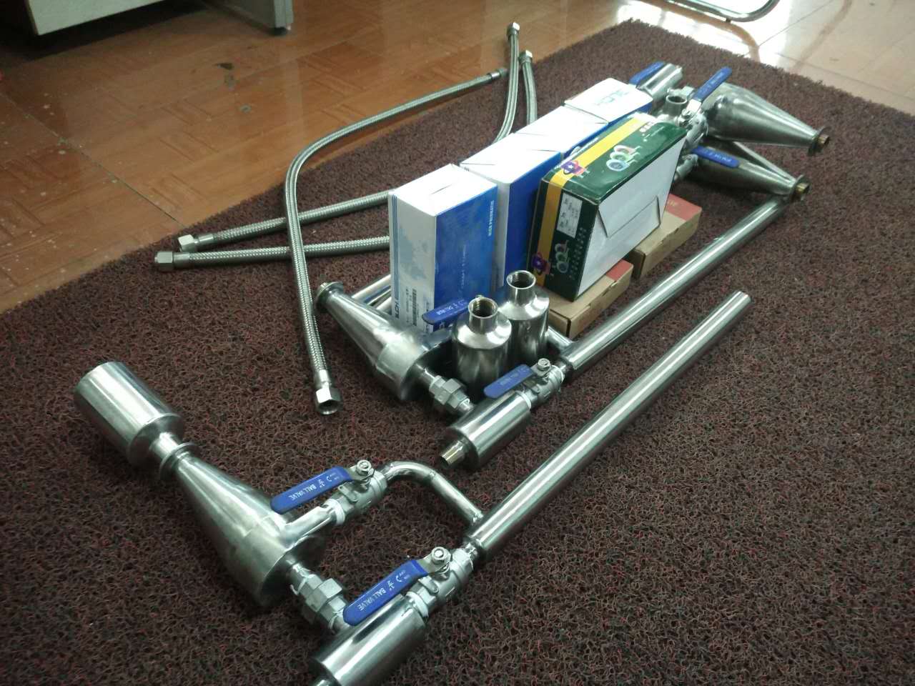
This product is Siying, with advanced working principle, strong self adjustment ability, and stable liquid level control- Mechanical moving parts, electrical components, and small size make the structure and system simple, easy to install, safe and reliable, and can be driven by any external force for a long time.
After applying the type water level controller, the workload of on-site maintenance and operation has significantly decreased, saving repair costs and reducing labor intensity. Secondly, due to the lack of pneumatic and electric thermal control systems, as well as complex thermal auxiliary equipment, the water level controller reduces maintenance personnel and greatly improves the operational management level of the equipment. Users refer to it as maintenance equipment.
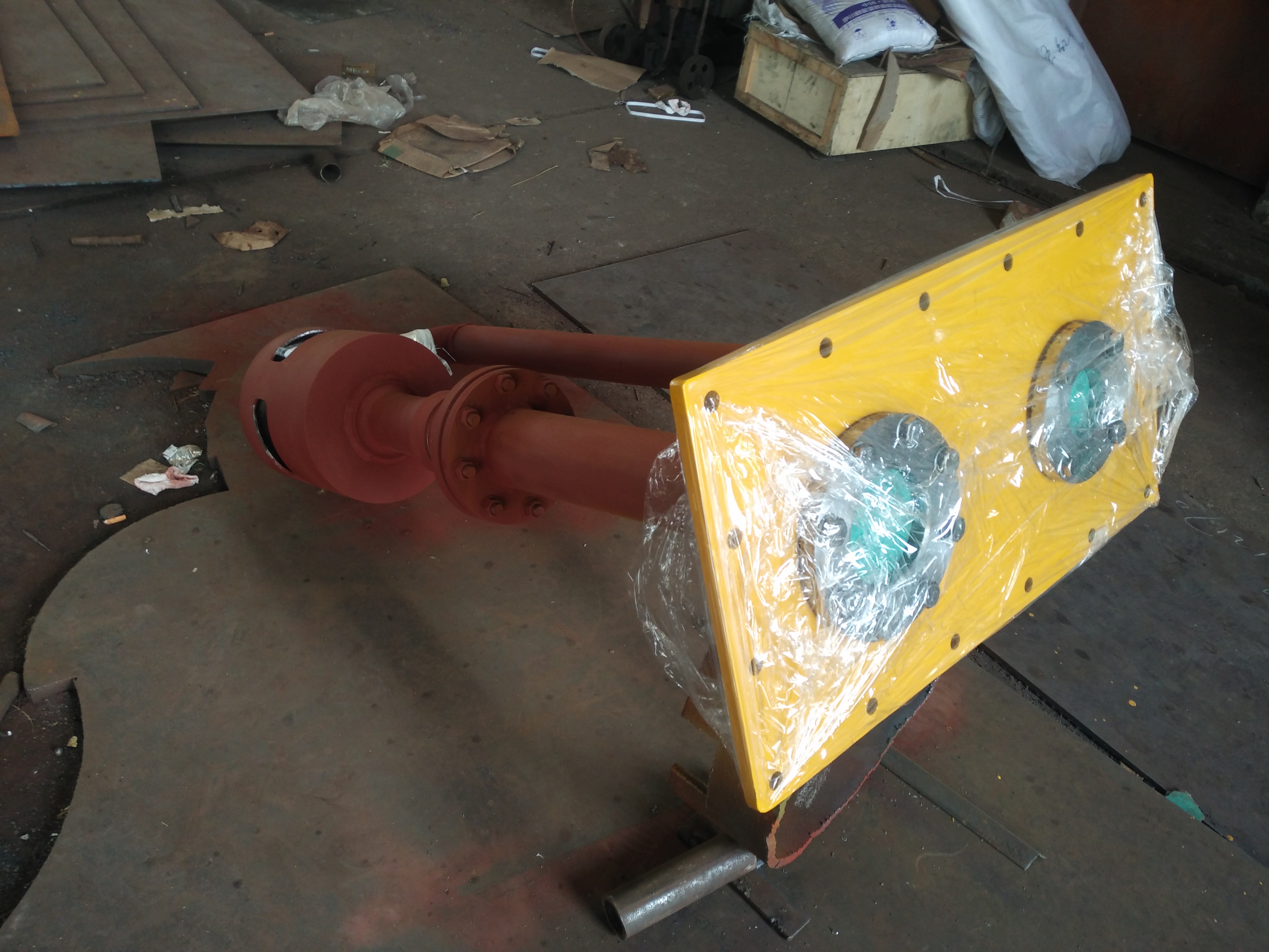
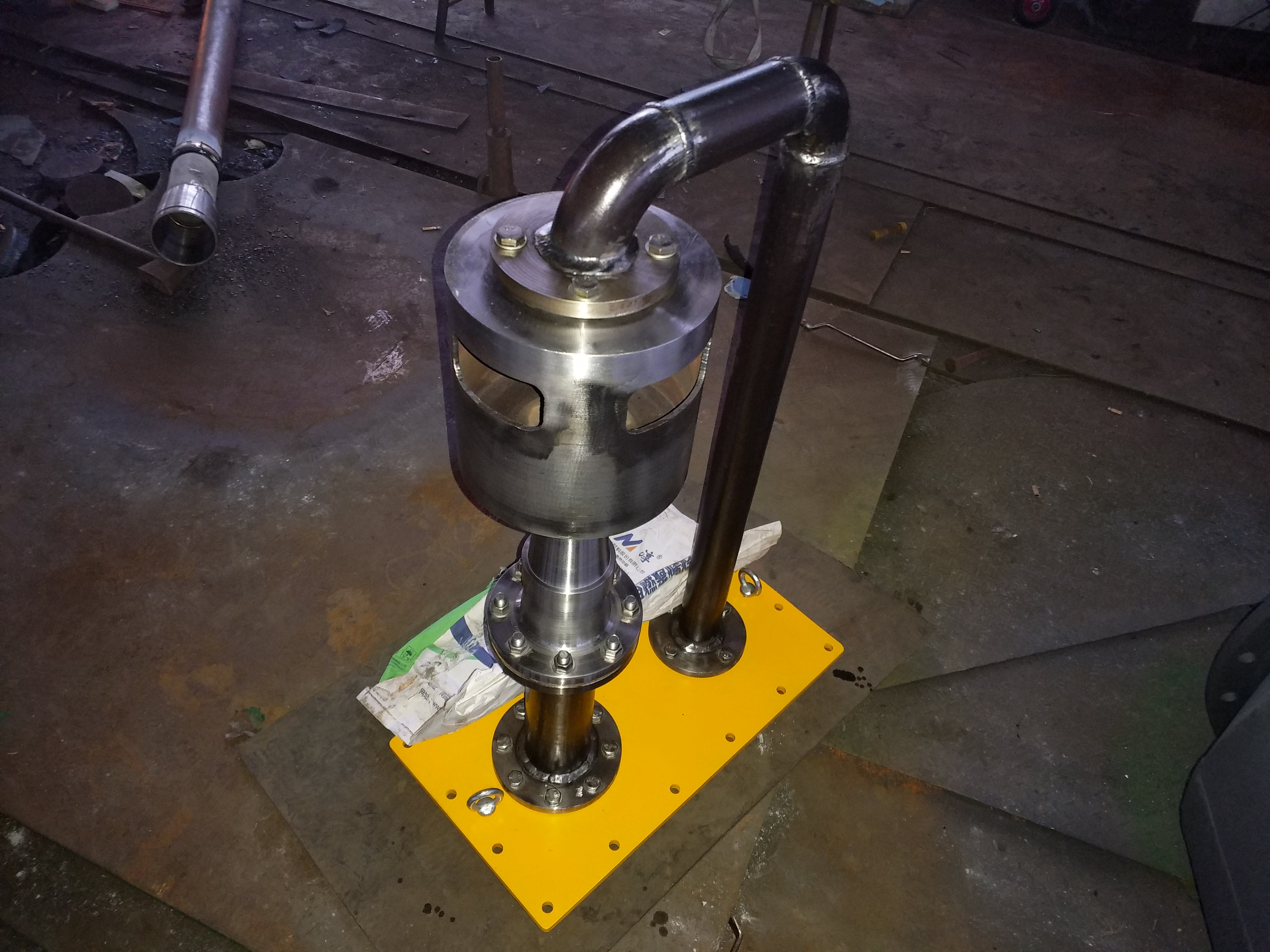
2、 Working principle of self regulating water level controller for gas-liquid two-phase flow
The self regulating liquid level controller for gas-liquid two-phase flow is a fully conceptual liquid level controller designed based on fluid mechanics theory and control principles, utilizing the flow of gas-liquid two-phase flow. It belongs to self operated intelligent regulation and requires a small amount of steam (about 1-2% of the displacement) as the driving force of the machine. The liquid level controller consists of a regulator and a signal tube (see Figure -). The connection system of the controller on the heater of the thermal power plant is shown in the figure. The function of the signal tube is to send water level signals and transmit regulating steam; The function of the regulator is to control the outlet water volume, which is equivalent to the automatic regulation system. The regulating principle is that when the water level of the heater rises, the water level in the signal tube also rises, resulting in a decrease in the amount of regulating steam sent. As a result, the amount of steam flowing through the regulator two-phase flow decreases and the amount of water increases, leading to a decrease in the water level of the heater. The opposite is also true. Thus, automatic control of the water level of the heater has been achieved.
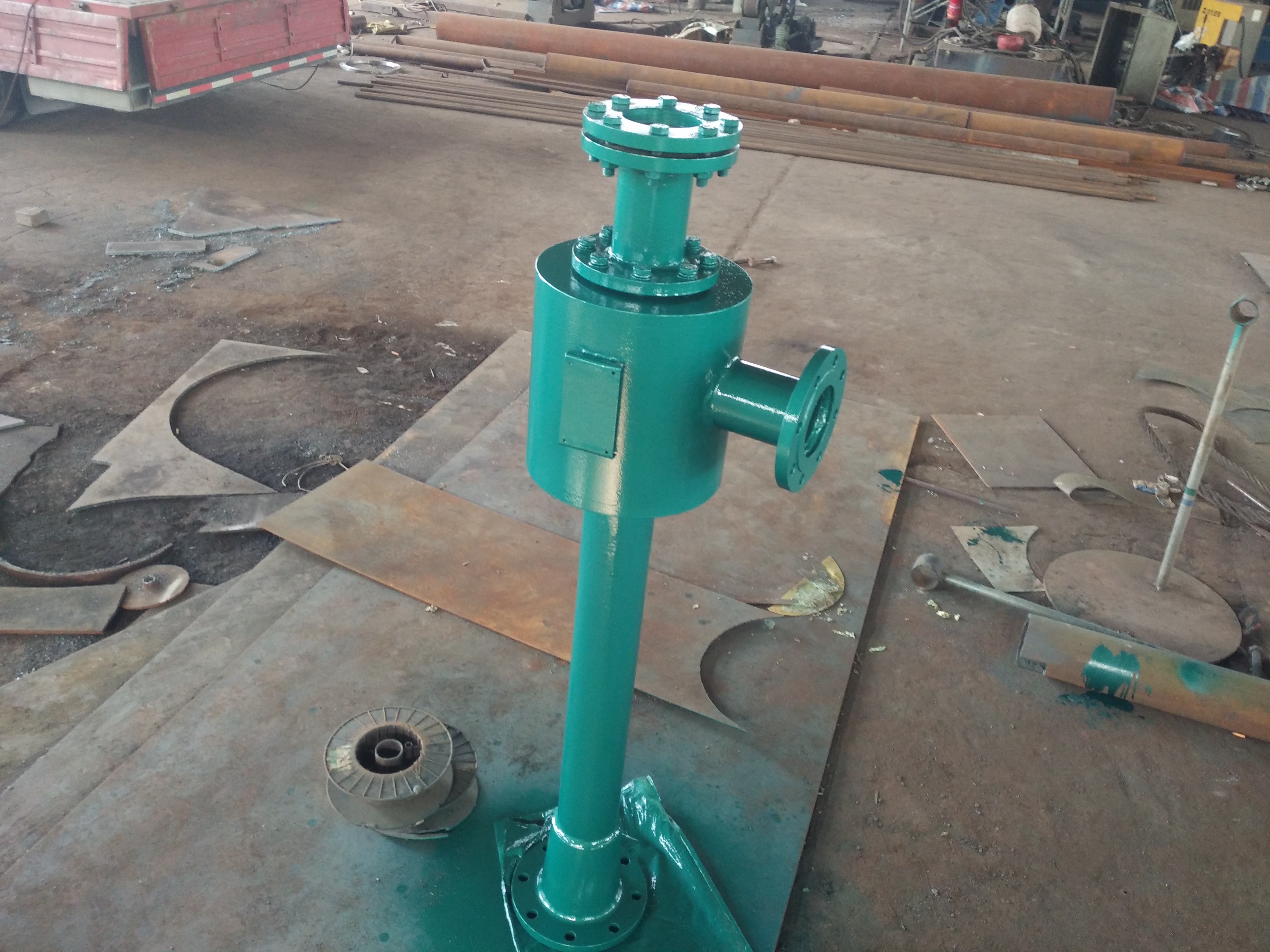
4、 Installation and debugging of self regulating water level controller for gas-liquid two-phase flow
-Installation
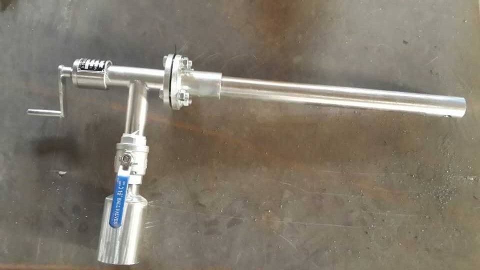
1. The transmitter must be vertical, and the upper branch pipe should be connected to the steam balance pipe of the heater. The lower branch pipe should be connected to the horizontal balance pipe of the heater.
2. The steam balance pipe should be connected to the heater at a low water level when the heating connecting pipe is above the warning water level.
3. Adjuster - placed horizontally. Different situations may also be placed vertically. Install in the direction of heated water outlet as much as possible.
4. Whether it is the transmission or adjusting the connection, the shorter the connecting pipe, the fewer the bends.
(2) Debugging
(1) Open various valves on each drainage pipeline and check if the water level gauge and water level controller are sensitive.
(2) The drainage capacity of the heating pipeline must be maintained at - high load.
(3) When debugging two or more water level controllers in a chain, proceed from high pressure to low pressure in sequence.
(4) Fully open signal pipeline regulating valve 4, fully open maintenance valve 5, close bypass valve 1 and regulating valve 2. When the water level slowly rises to the positive water level, then open regulating valve 2. Observe the water level and continue to use regulating valve 2 to close and gradually adjust until the water level can automatically maintain a stable state.
(5) If there is full water during the height process, the bypass valve 7 can be opened appropriately.
5、 Notice on Ordering of Self regulating Water Level Controller for Vapor Liquid Two Phase Flow
1. Steam pressure of heater (MPa):
2. Steam temperature of heater (℃):
3. Steam flow rate of heater (t/h):
4. Heater drainage capacity (- when large, t/h):
5. Heater drain pipe diameter (mm):
6. Final - High pressure heater drain to deaerator height (m):
7. Deaerator pressure (MPa):
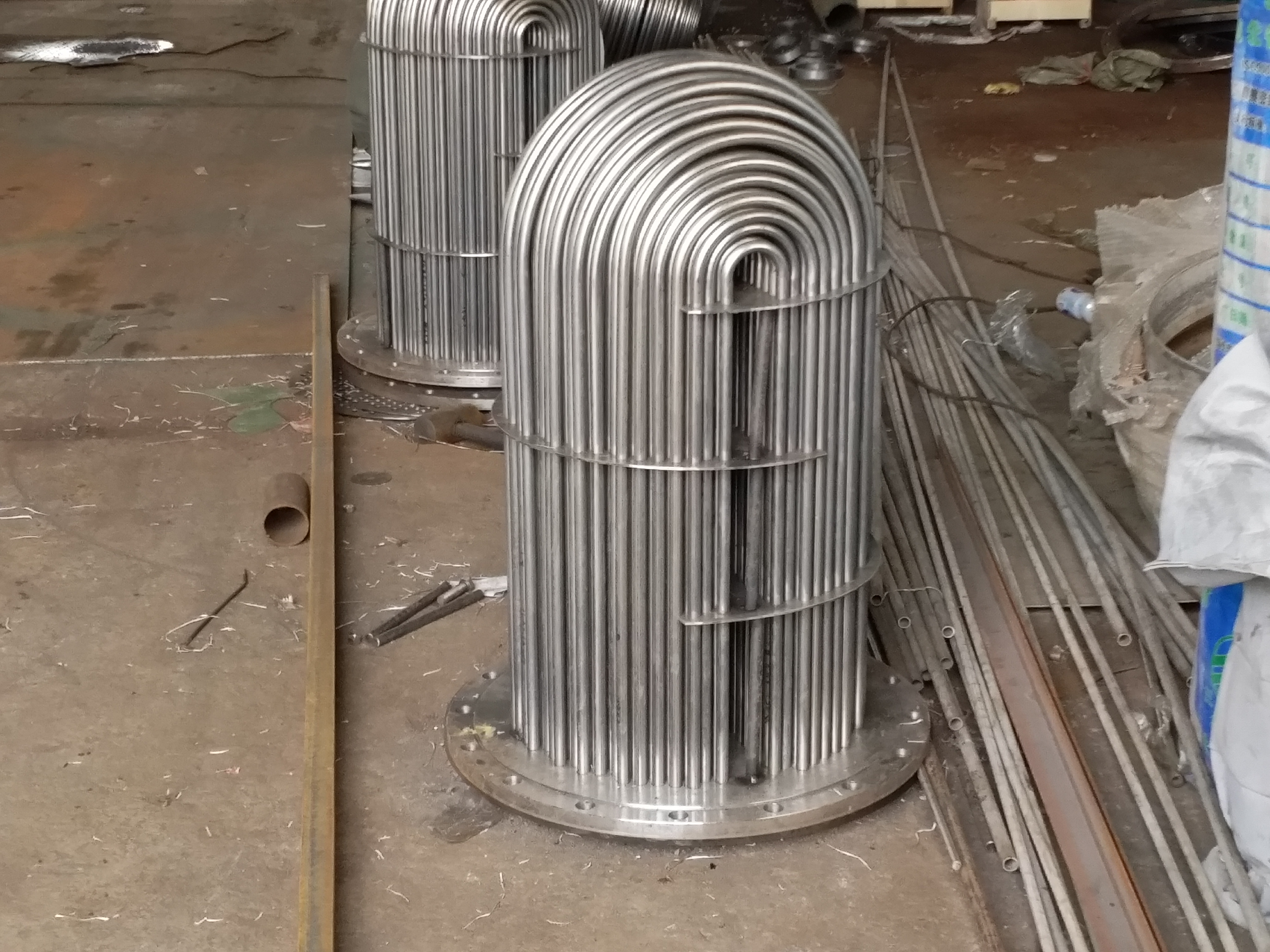
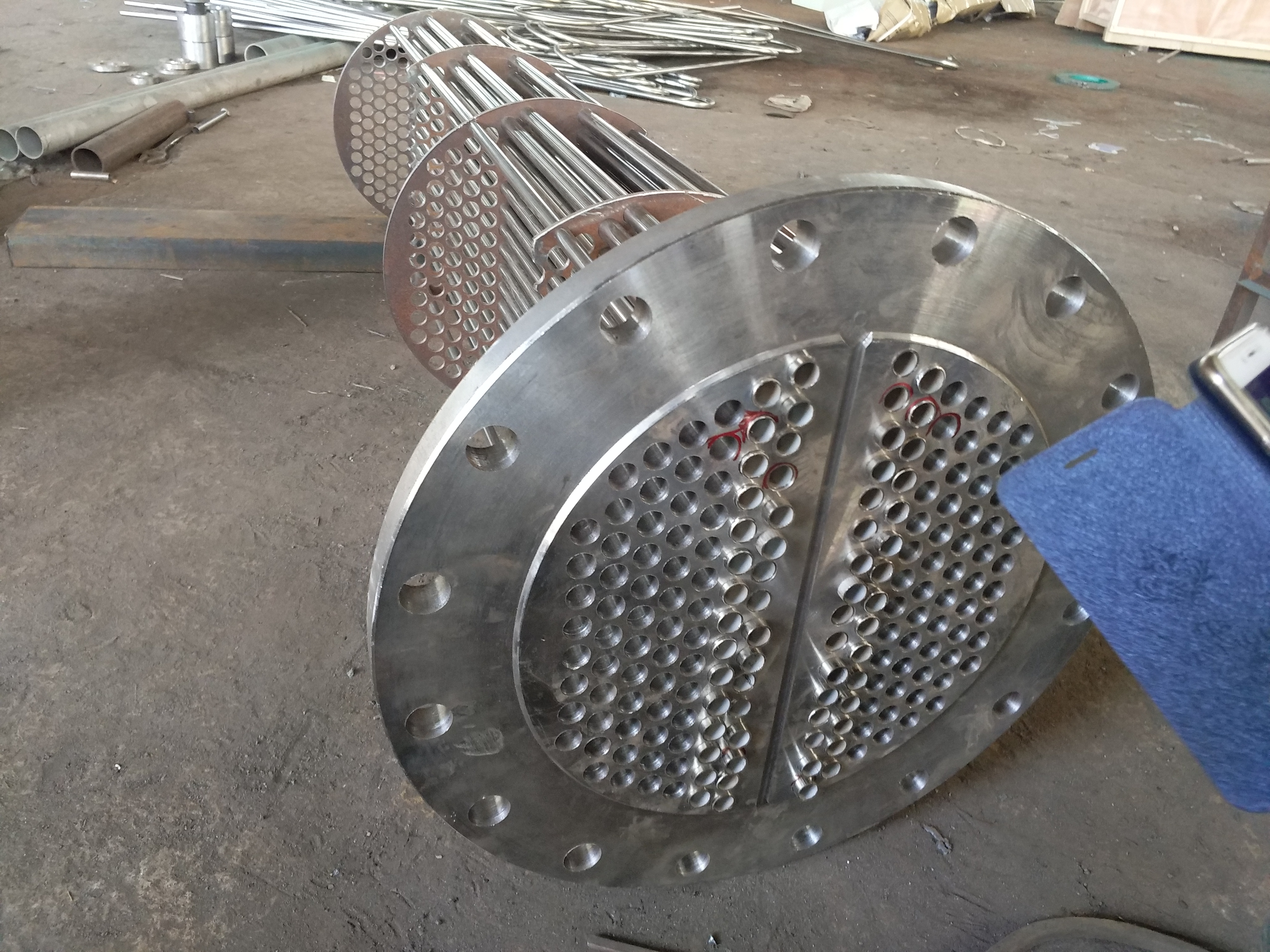
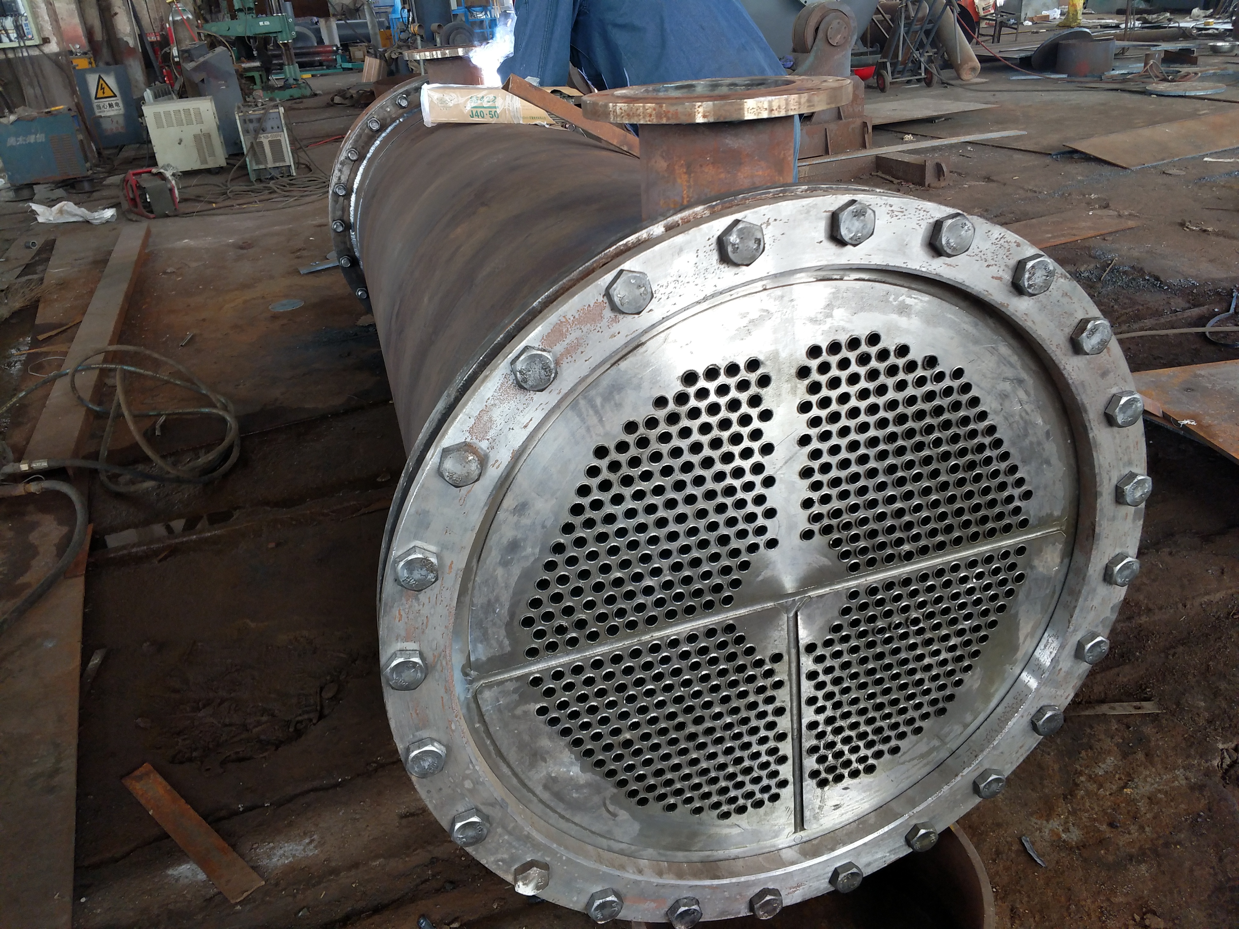
The steam seal heater adopts a horizontal U-shaped surface heat exchan...

The steam seal cooler generally adopts a horizontal U-shaped surface h...
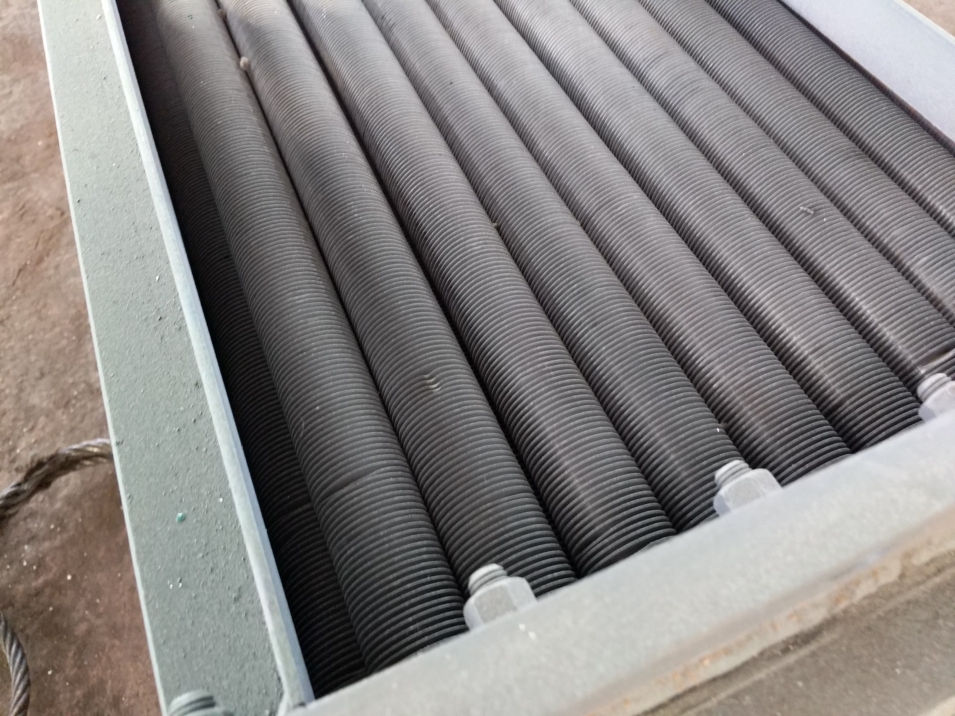
The air cooler adopts finned tube material, single metal finned tube a...
The waste heat recovery device, also known as the energy collector and...
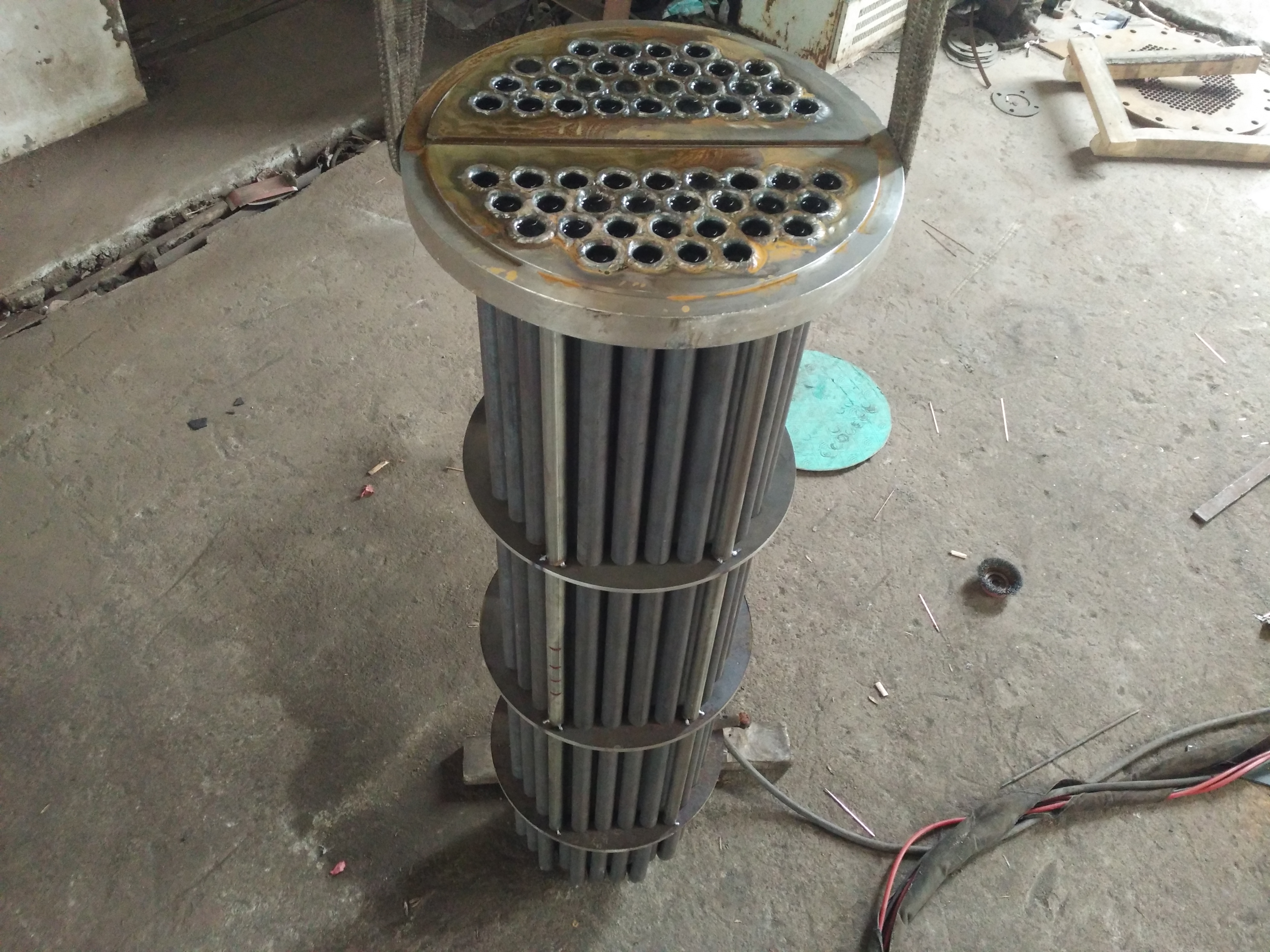
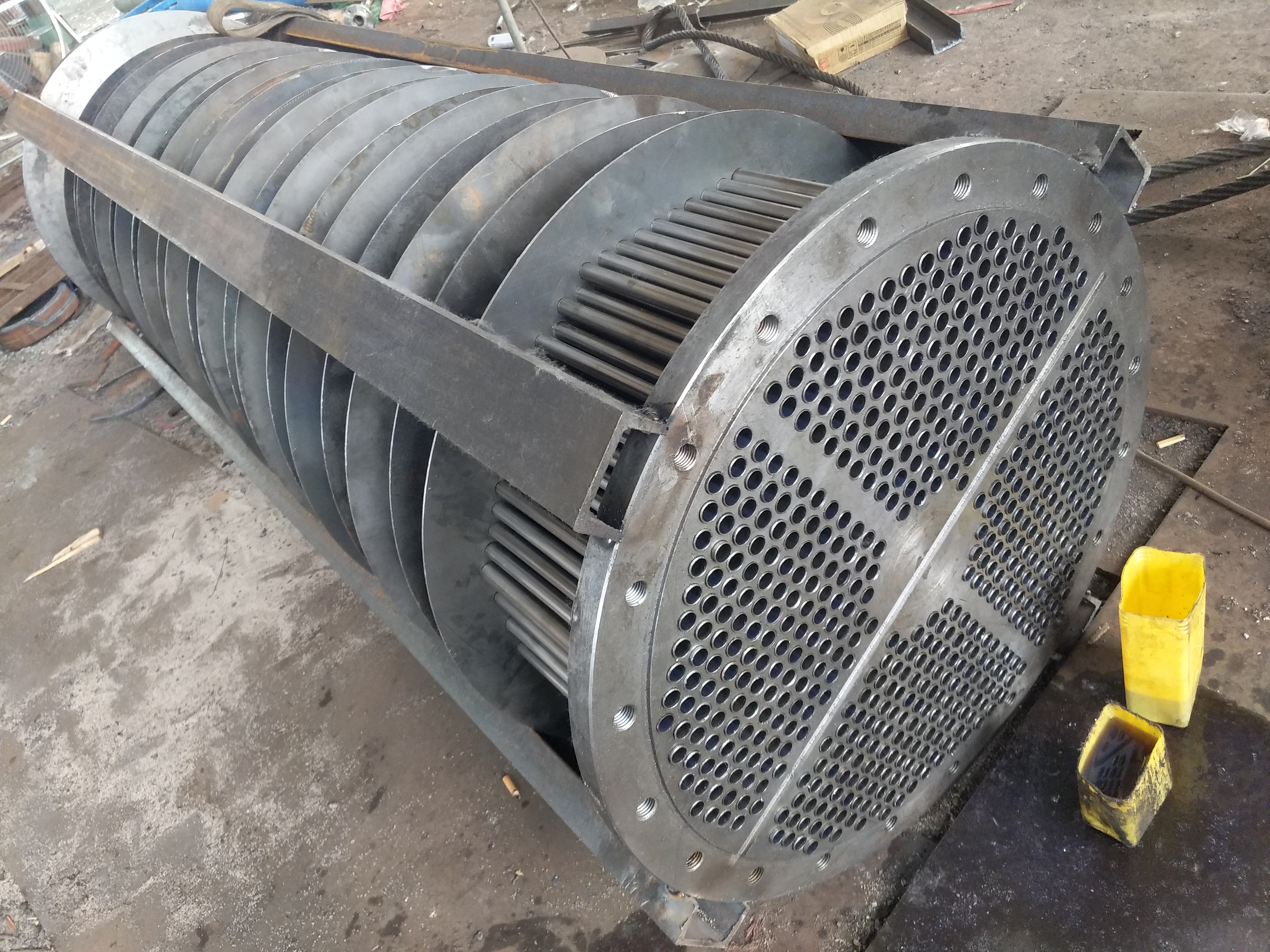
The U-shaped tube is used as a cooling tube for heat exchange tubes, a...

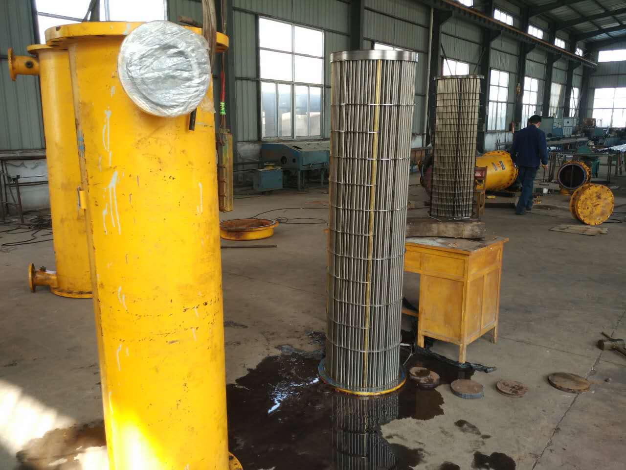
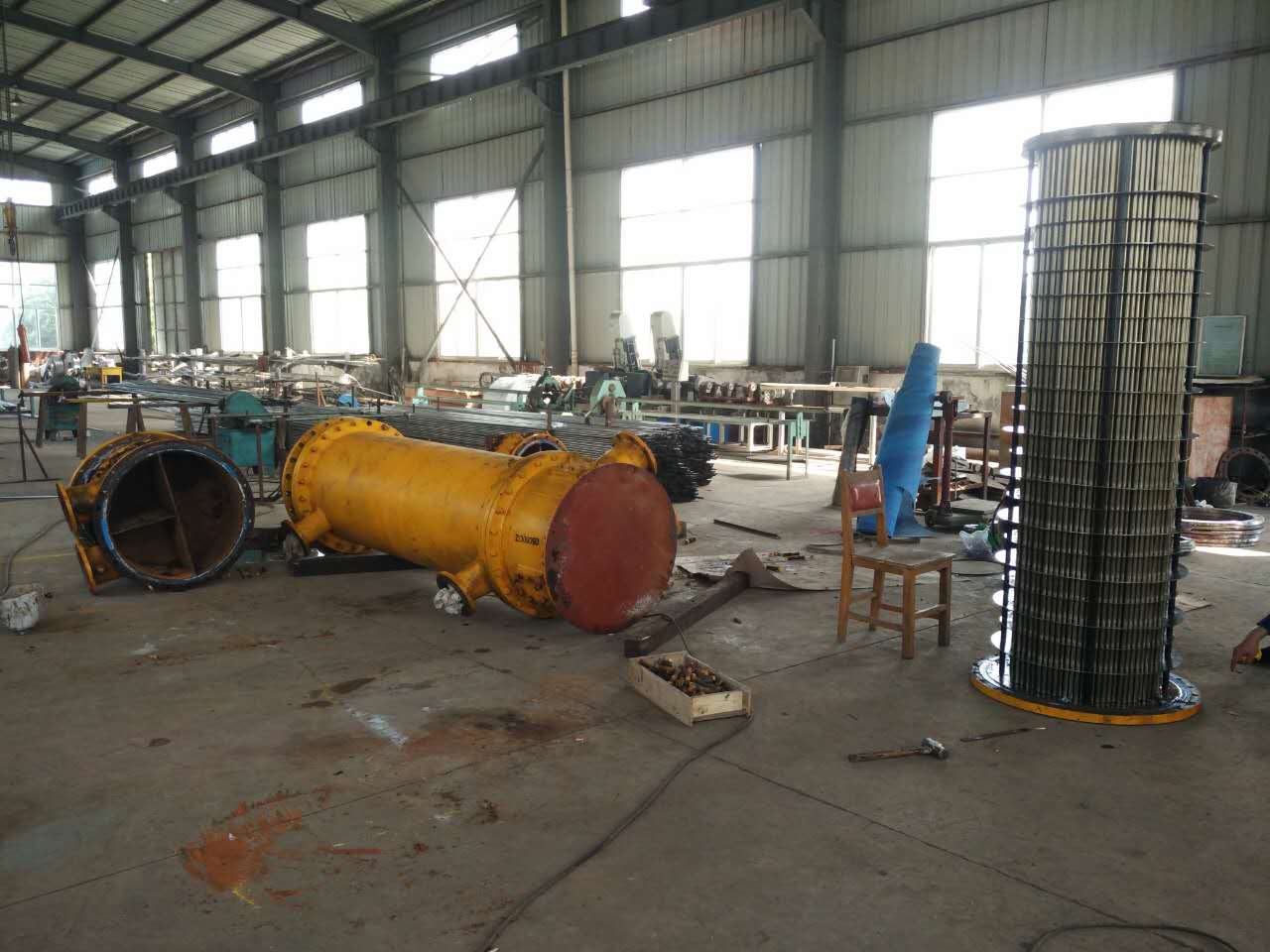
Overview of condenser tube replacement and condenser stainless steel t...
Welded steel pipes (also known as slotted pipes and welded pipes) are ...
Welded steel pipes (also known as slotted pipes and welded pipes) are ...
Manufacturer of shaft seal heaters, also undertaking pipe replacement ...
Welded steel pipes (also known as slotted pipes and welded pipes) are ...
Steam turbine oil-water cooler pipe replacement, marine oil-water cool...
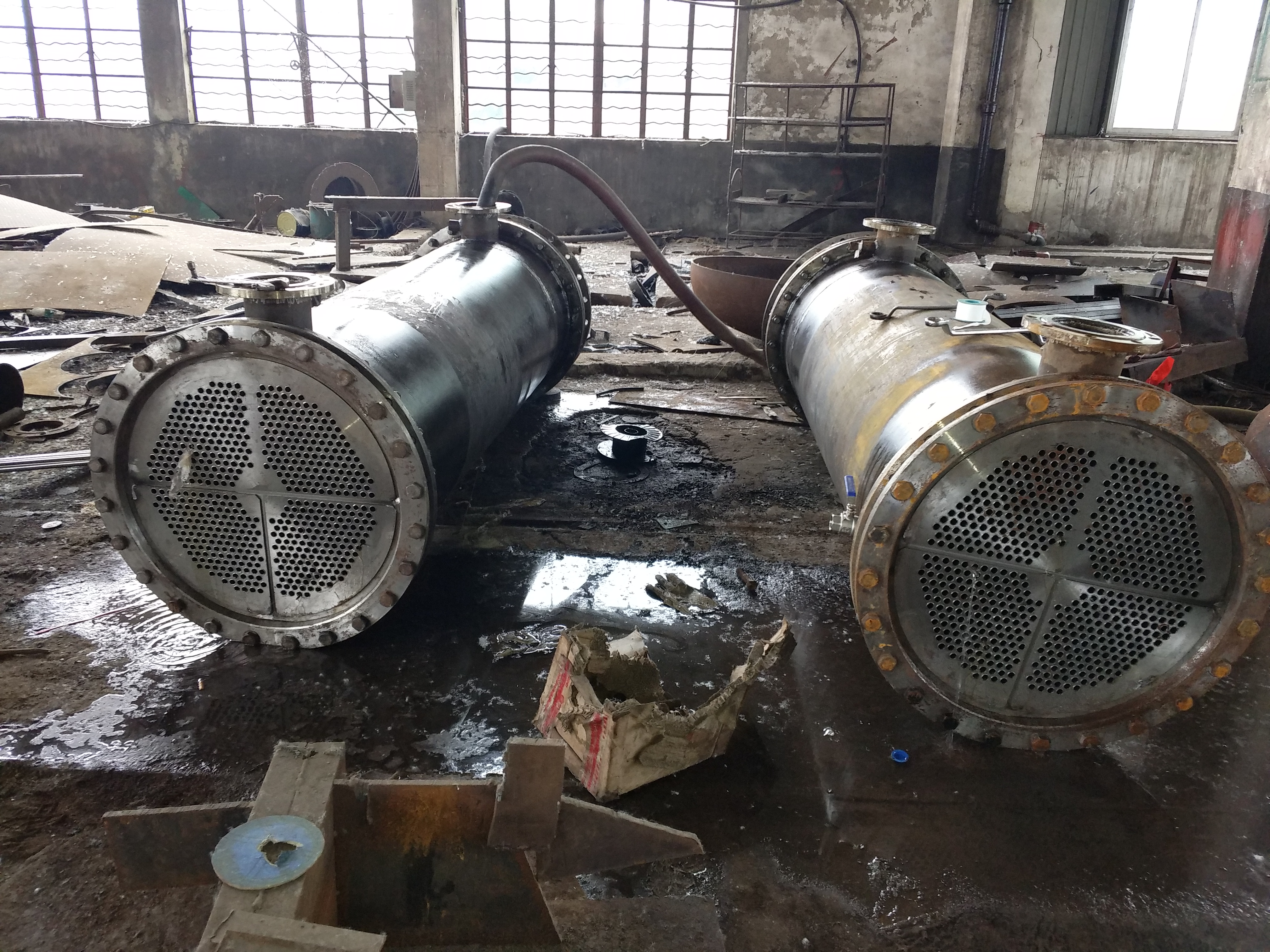
When purchasing a column type oil cooler for tube and core replacement...
The automatic steam liquid two-phase flow steam trap, also known as th...

The oil injectors produced by Lianyungang Lingdong Electromechanical E...
The oil injector is composed of a nozzle, a filter screen, an expansio...
A steam injector is a device that is powered by steam and is needed in...

Calculation of cooling area of sampling cooler 1: If the sample flow r...
The sampling of fly ash sampler is selected on the flue between the ou...
The use of carbon steel material in coal powder samplers has caused ma...
The working status of the oil injector and main oil pump, the analysis...

The oil supply and lubrication oil injectors are completely identical ...
The installation and operation of the coal powder sampler and mobile c...
The manual mobile coal powder sampler produced and manufactured by Lia...
The oil injector of Lianyungang Lingdong Electromechanical Equipment C...

Keep up on our always evolving product features and technology. Enter your e-mail and subscribe to our newsletter.
Copyright © 2012-2026 00LD连云港灵动机电设备有限公司遥遥制造汽液两相流液位自动疏水调节器、汽液两相流液位控制器、汽液两相流疏水器及油雾分离器、排油烟装置,可提供除氧器以及凝汽器换管改造、冷油器现场更换管束增容服务。 00ld.com 版权所有


