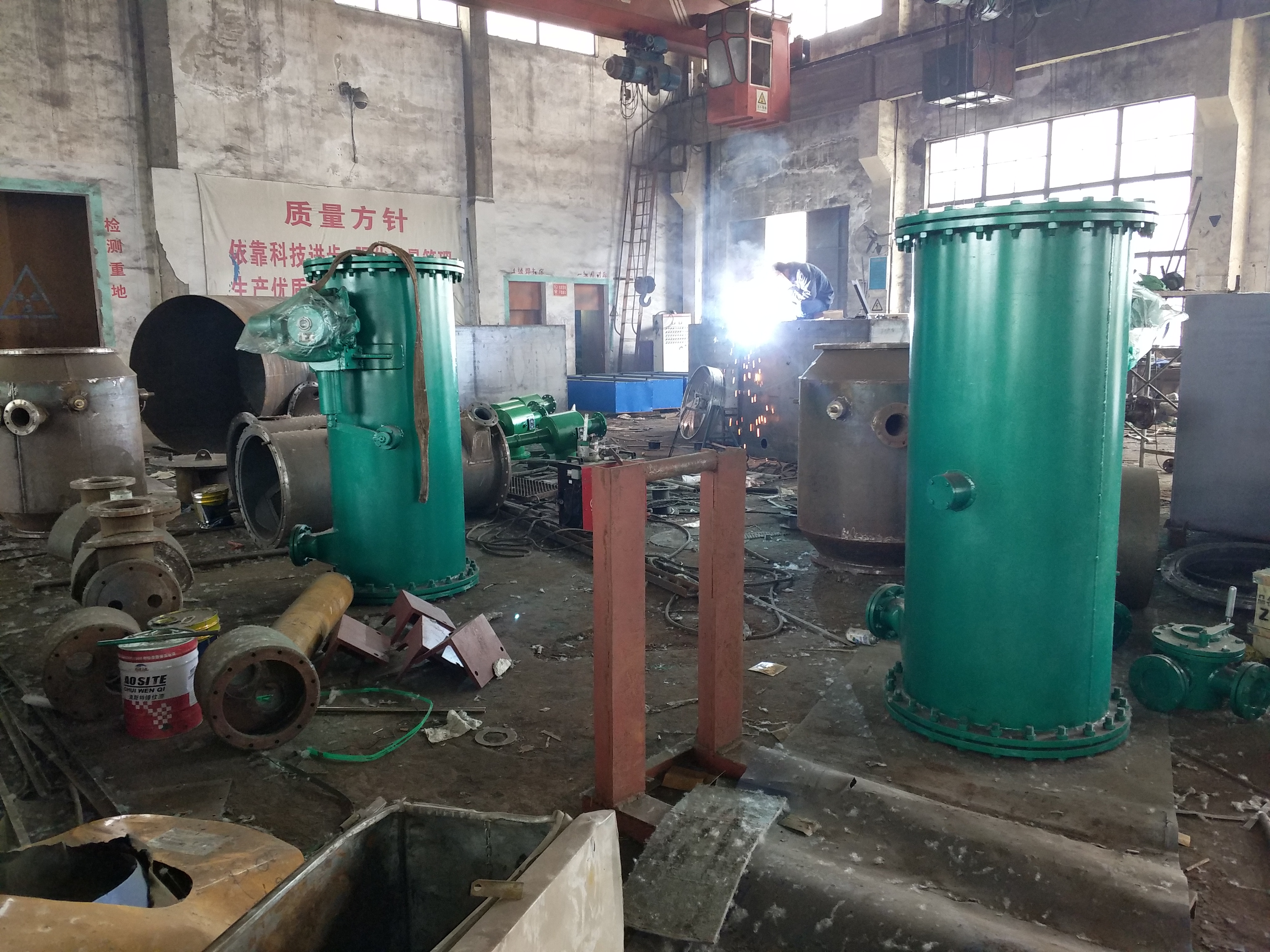
The rubber ball cleaning device is designed for cleaning the cooling pipes of the condenser during the operation of the steam turbine unit. The use of this device directly affects the degree of cleaning and heat transfer results of the steam turbine condenser.
The rubber ball cleaning device is an equipment that cleans the cooling pipes of the condenser during the operation of the steam turbine unit. The use of energy directly affects the degree of cleaning and heat transfer results of the steam turbine condenser. The scope of application is equivalent, it is not only suitable for cleaning steam turbine condensers, but also suitable for petroleum, petrochemical, chemical, and steel units; The cleaning of the cooling tubes of fixed tube plate heat exchangers has entered the market of central air conditioning (central air conditioning rubber ball cleaning system). The condenser rubber ball cleaning device can be put into use without reducing the load during continuous operation, and can always maintain the cleanliness of the cooling tubes, prolong their use, reduce labor intensity, and increase economic benefits. Rubber ball cleaning system is an indispensable device for improving the safe and economic operation of condensers and heat exchangers in power plants, petroleum, petrochemical, chemical, and steel enterprises. The rubber ball cleaning and manufacturing system consists of secondary filter screens, ball collecting nets, ball loading rooms, rubber ball conveying pumps, distributors, valves, pipelines, and electrical control cabinets. The use of rubber ball cleaning can clean the condenser without reducing the load of the unit, improve the heat transfer efficiency of the condenser, prevent the heat rate of the steam turbine from decreasing due to the increase of back pressure, and prevent the corrosion of the cooling pipes due to scaling, extending the use of the cooling pipes. It is an energy-saving and improving labor conditions equipment. Adopting a unit system for large units, that is, using a ball collecting net, a ball loading chamber, and a rubber ball conveying pump on each side of the condenser; For small units, a shared system is adopted.
Application of rubber ball cleaning device:
Rubber ball cleaning can clean the cooling pipes of the condenser without reducing the load of the unit, improve the heat transfer efficiency of the condenser, prevent the heat rate of the steam turbine from decreasing due to the increase of back pressure, and prevent the corrosion of the cooling pipes due to scaling. It prolongs the use of the cooling pipes and is a energy-saving and labor condition improving equipment.
Rubber ball cleaning device system - Composition:
The rubber ball cleaning equipment consists of components such as a ball collecting net, a splitter, a ball loading chamber, a rubber ball conveying pump, and an electrical control cabinet. For large units, a unit system is adopted, which means that each side of the condenser is equipped with a ball collecting net, a ball loading chamber, and a rubber ball conveying pump; For small units, a shared system is adopted, which means that both sides of the condenser share a ball loading chamber, a rubber ball conveying pump, and each side has a ball collecting net, a secondary filter screen, and a splitter.
Working principle of rubber ball cleaning device:
Choose a suitable sponge rubber ball, with a wet diameter slightly larger than the inner diameter of the cooling tube (about 1-2mm), and a wet ratio similar to water. Place sponge rubber balls into the ball loading chamber from the hand hole, with a quantity of 7% to 13% of the cooling pipes in the inlet chamber of the condenser. Then start the rubber ball pump and open the control valve of the system. Under the action of the rubber ball pump, the rubber ball is driven by a water flow slightly higher than the pressure of the circulating water and sent into the inlet pipe of the circulating water. With the flow of the circulating water, the rubber ball enters the water chamber of the condenser. Due to the fact that the rubber ball is a micro porous and soft elastic body, it is squeezed through the cooling pipe under the pressure difference between the inlet and outlet of the circulating water, and the inner diameter of the cooling pipe is cleaned again, causing the dirt on the inner wall of the pipe to be carried out with the water flow. After passing through the condenser pipe, the rubber ball enters the ball collecting net together with the circulating water. Under the obstruction of the ball collecting net plate, the rubber ball is separated and then pumped out by the rubber ball conveying pump before entering the ball loading chamber. In this cycle, the rubber ball continuously and automatically cleans the inner wall of the condenser cooling pipe to keep it clean.
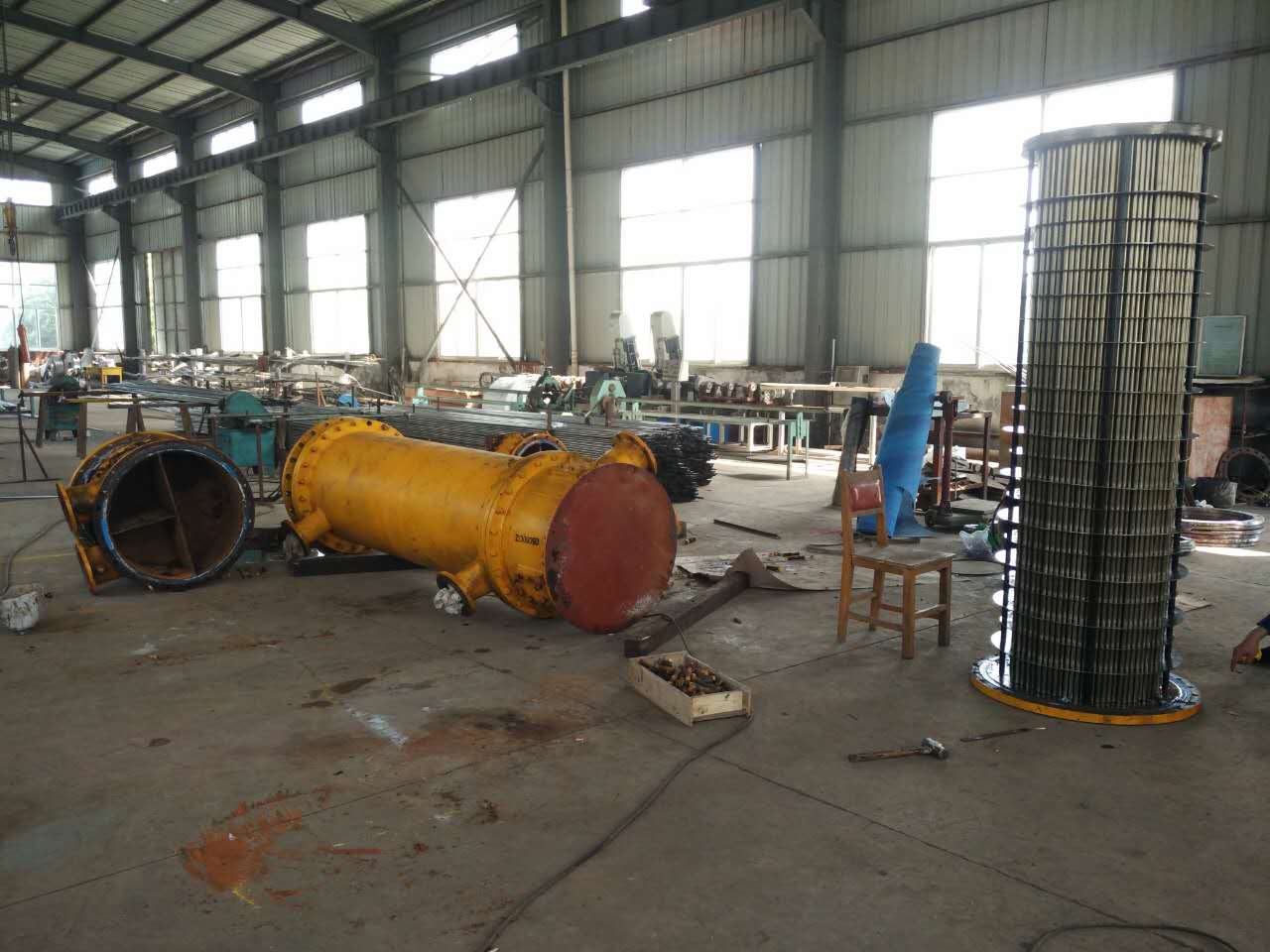
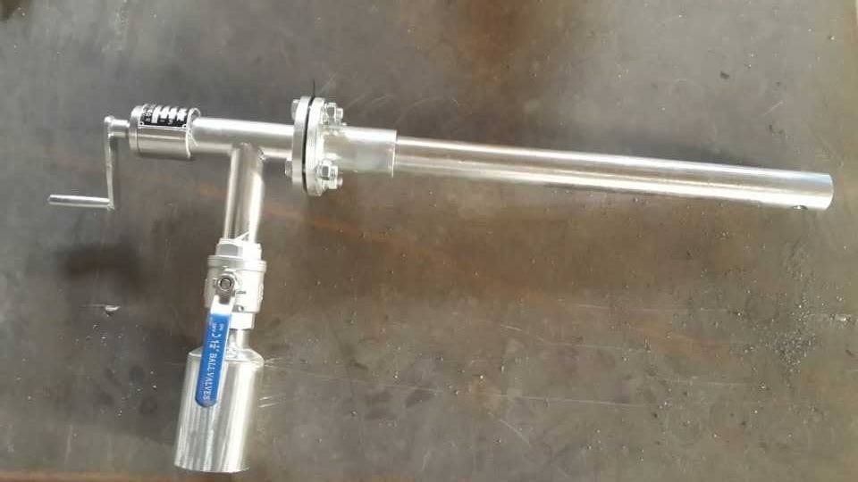
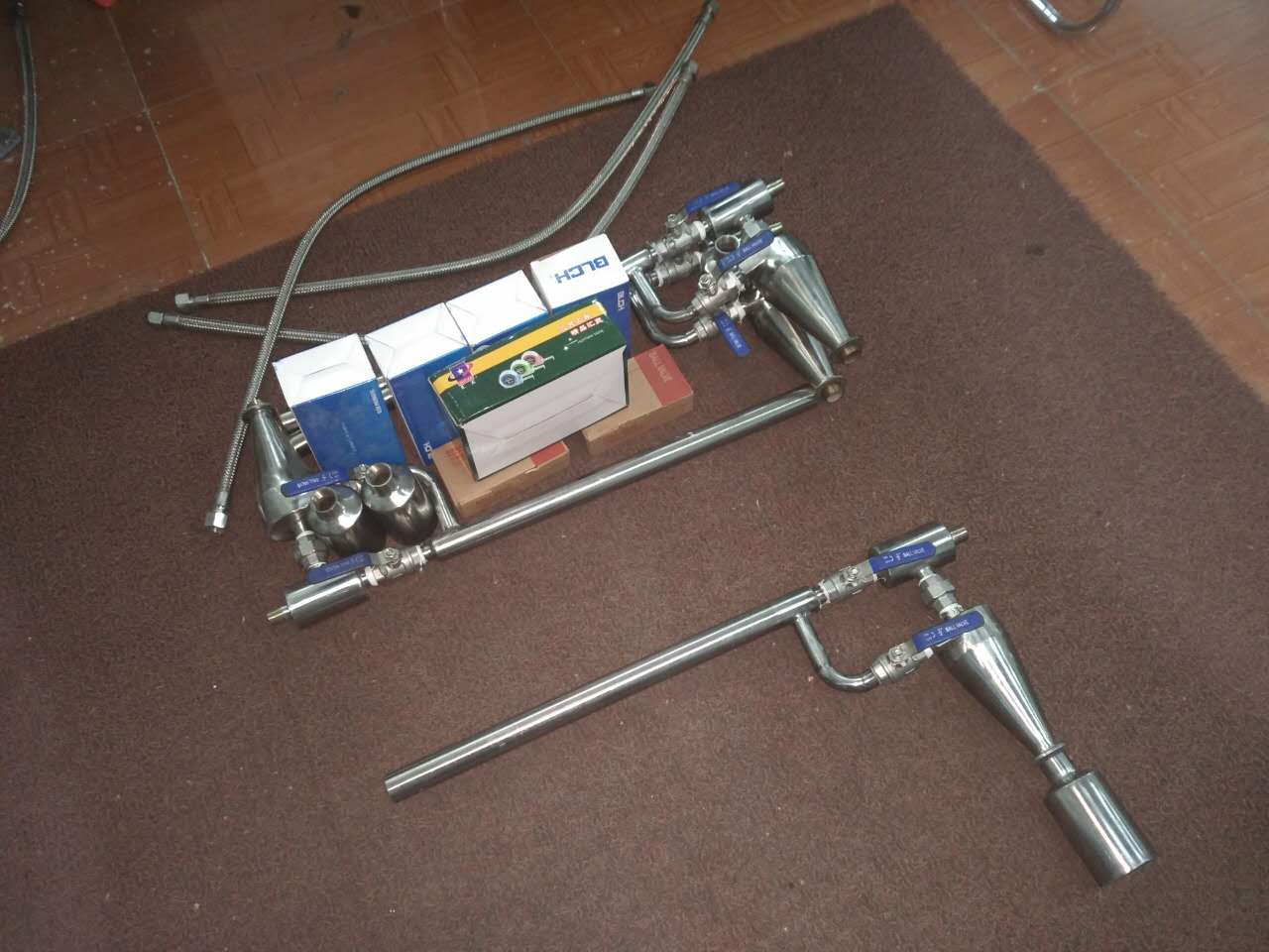
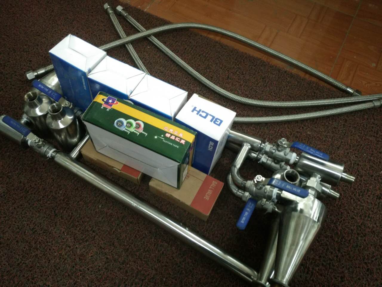
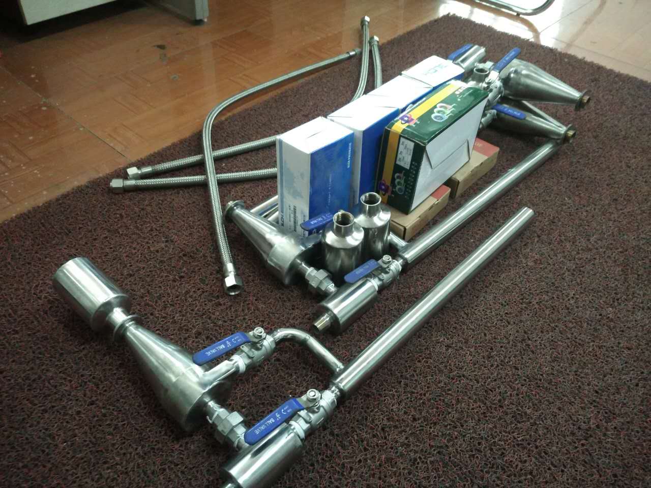
Assembly diagram of rubber ball cleaning device
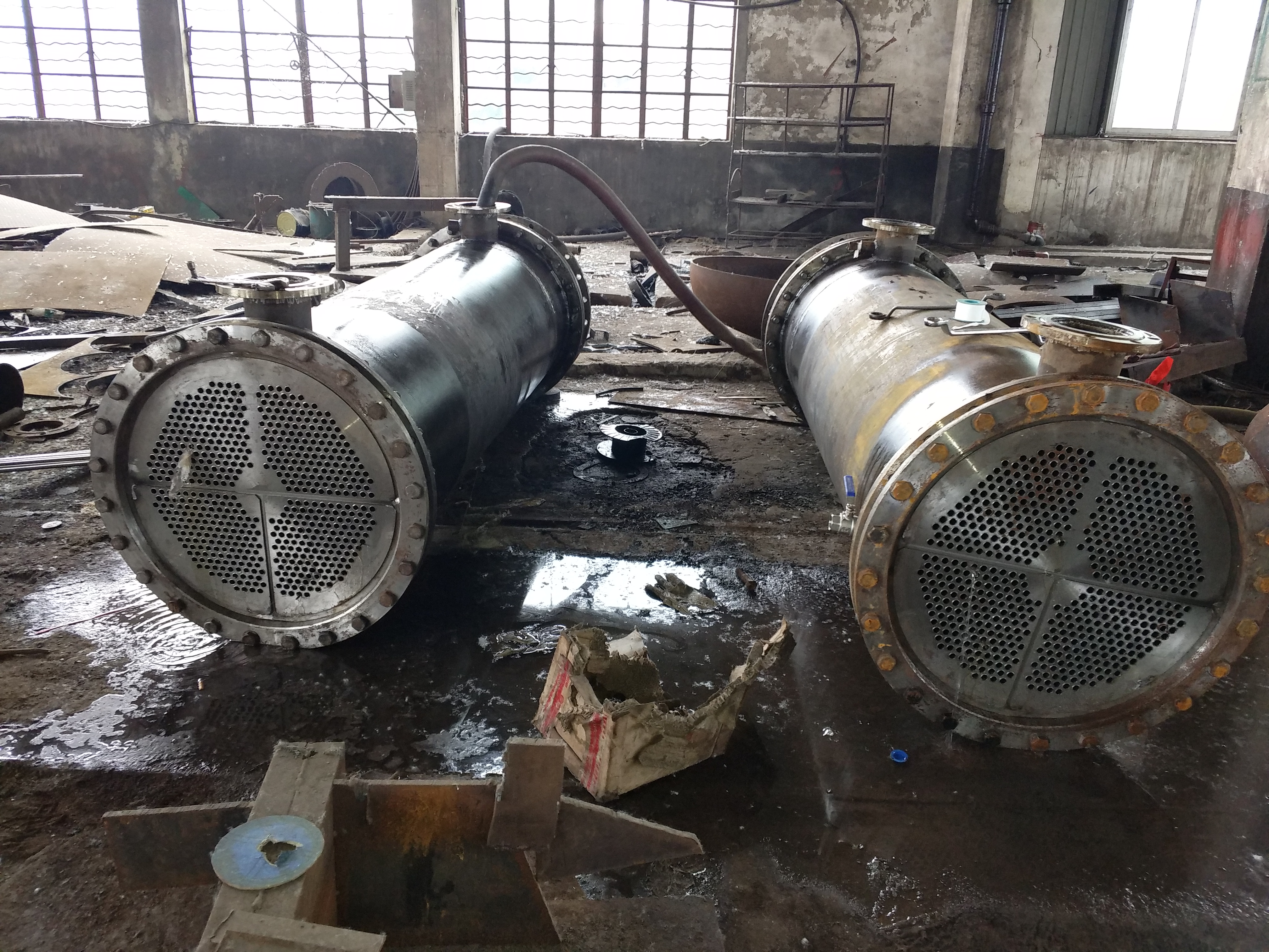
Rubber ball cleaning system - Introduction to each component equipment (ball collecting net):
1. Collecting net:
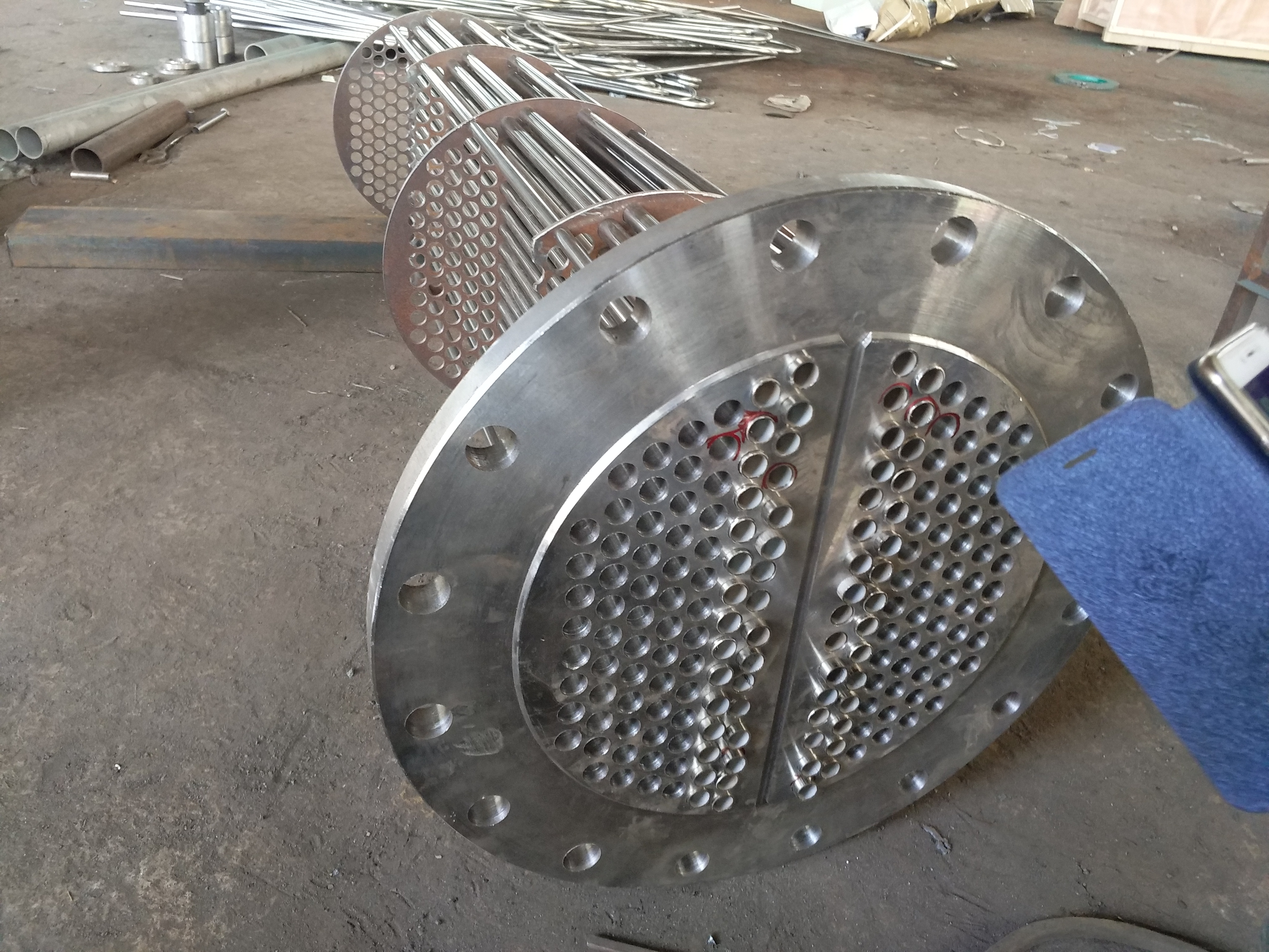
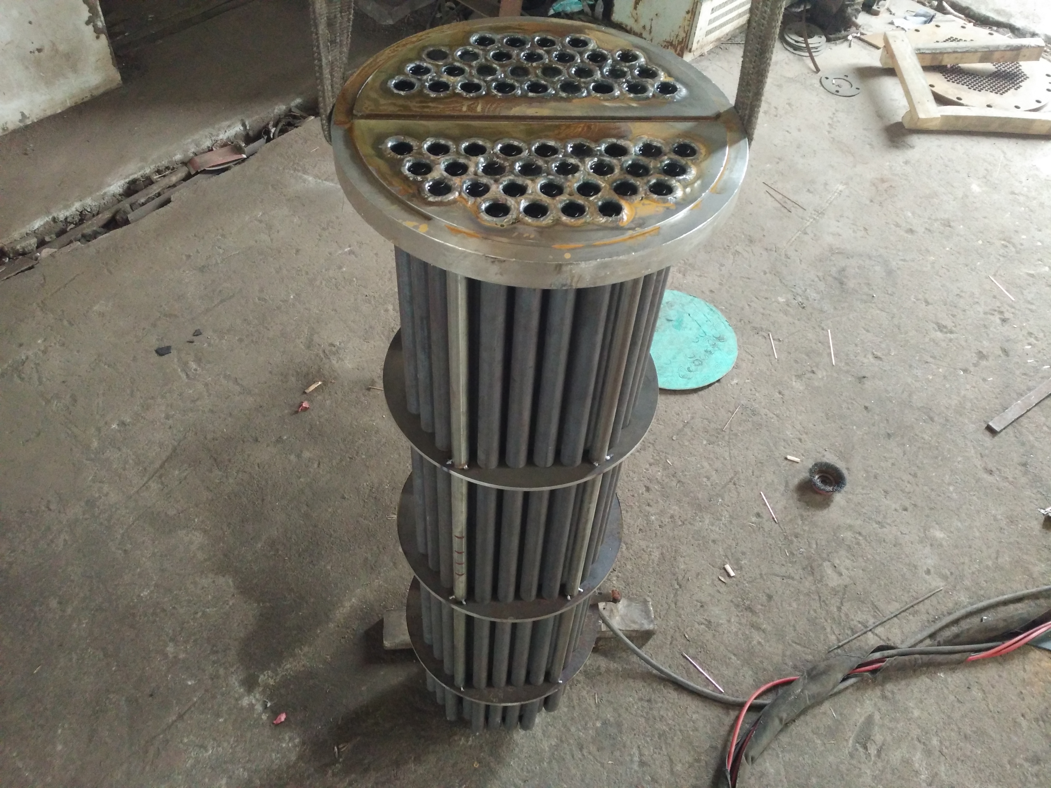
The ball collecting net is a key equipment for the cleaning device of the condenser rubber ball - the recycling rubber ball. It is installed in the outlet pipeline of the condenser's circulating water. After the circulating water and rubber ball from the condenser pass through the ball collecting net, the circulating water flows out from the ball collecting net plate, and the rubber ball is collected by the ball collecting net and flows into the ball loading room through the rubber ball outlet pipe, for recycling.
The second-generation collection net designed and produced by our unit adopts both internal and external technology design.
Collecting net assembly diagram
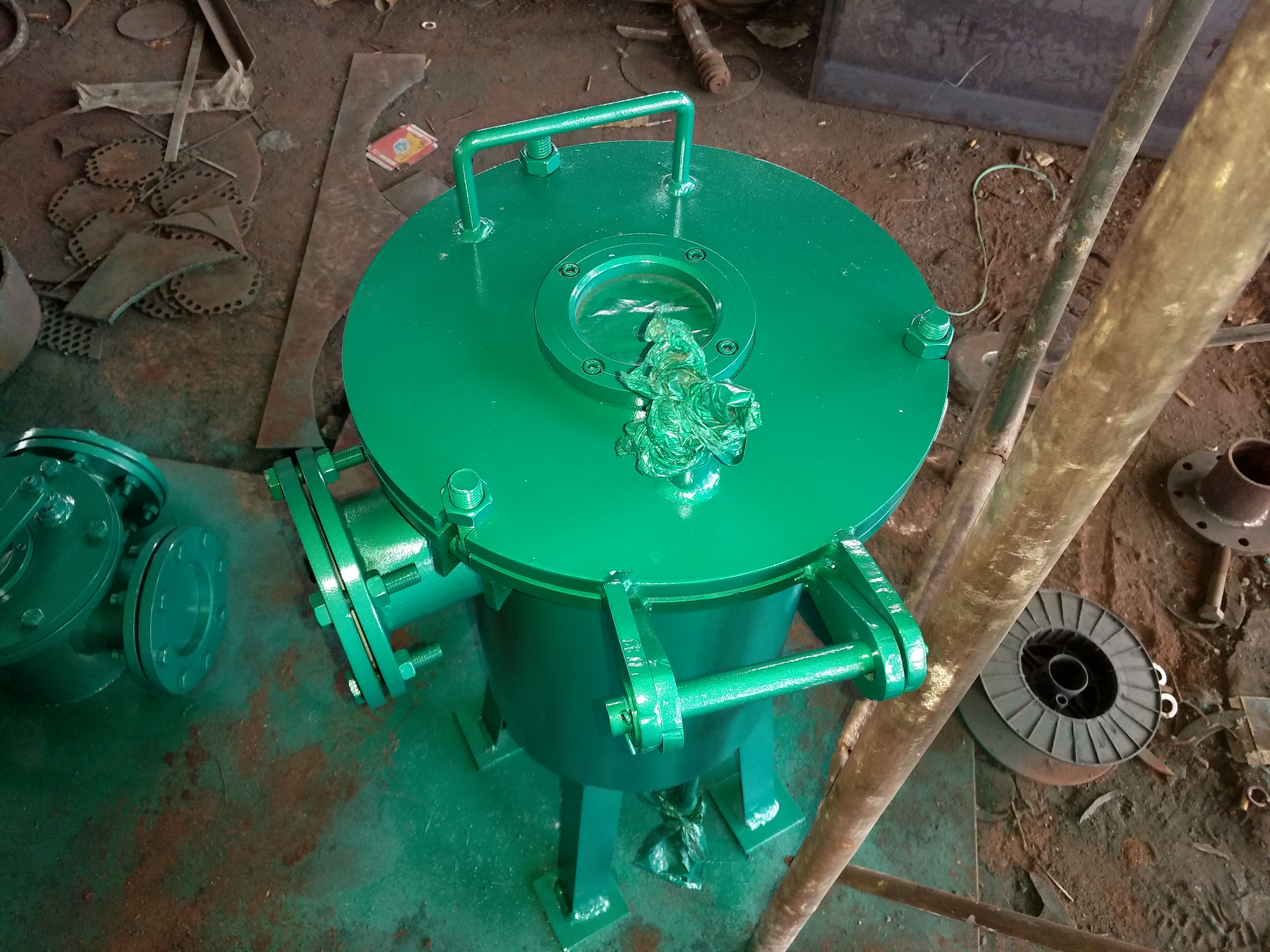
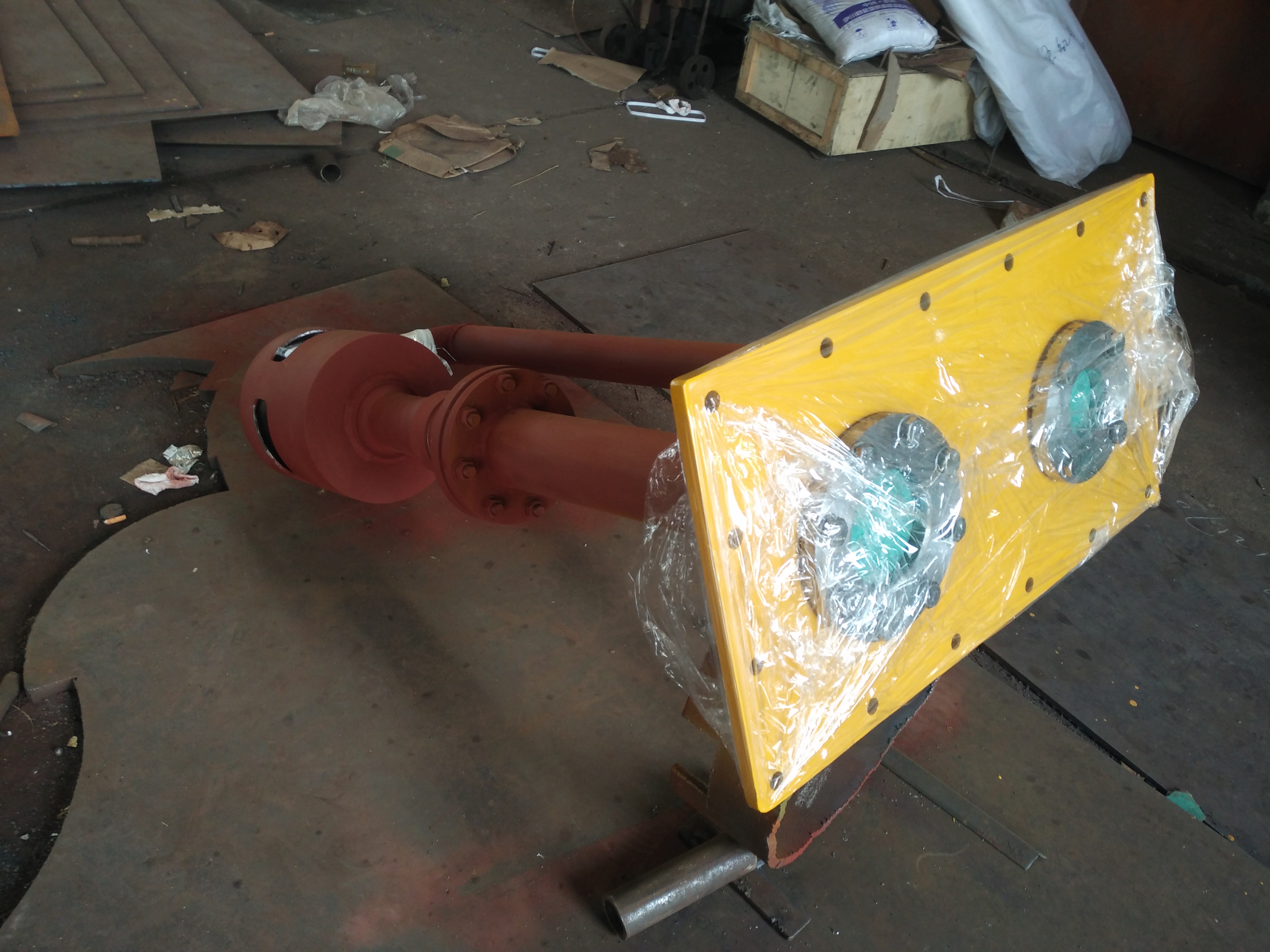
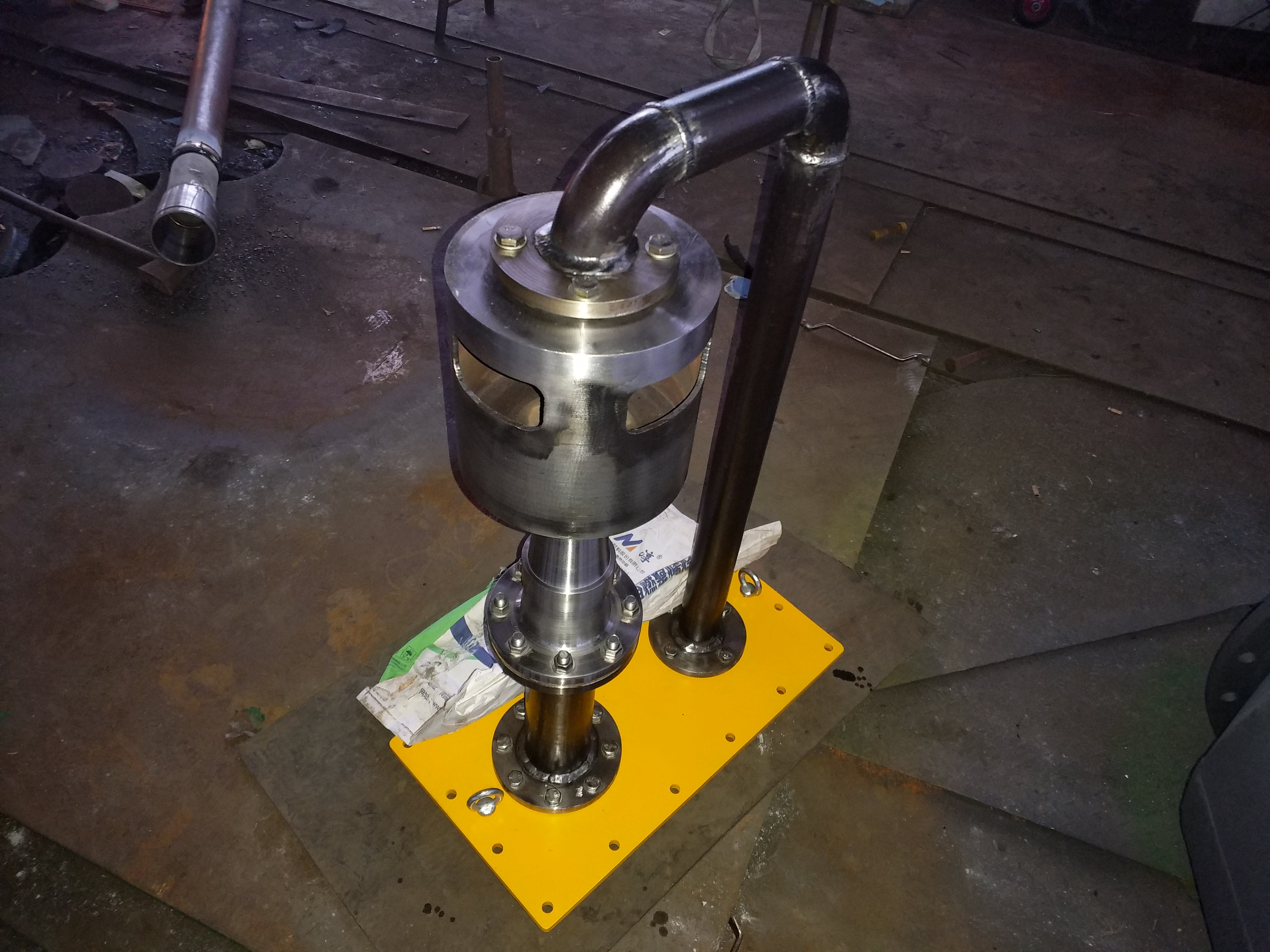
2. Ball loading room:
The ball loading chamber is a condenser rubber ball cleaning device - a type of equipment used for adding, collecting, replacing balls, and observing the operation of rubber balls. It consists of a casing, a hopper, a switching valve, etc., and is equipped with observation windows, steam and water release valves, etc.
>The rubber ball conveying pump is a type of obstacle centrifugal pump, which is the power equipment for the cleaning device of the condenser rubber ball and the circulation conveying of the rubber ball. During the transportation of rubber balls, there will be no blockage or cutting of the rubber balls. In addition to being suitable for conveying rubber balls, it can also be used for conveying solid substances with low wear and tear in liquids.
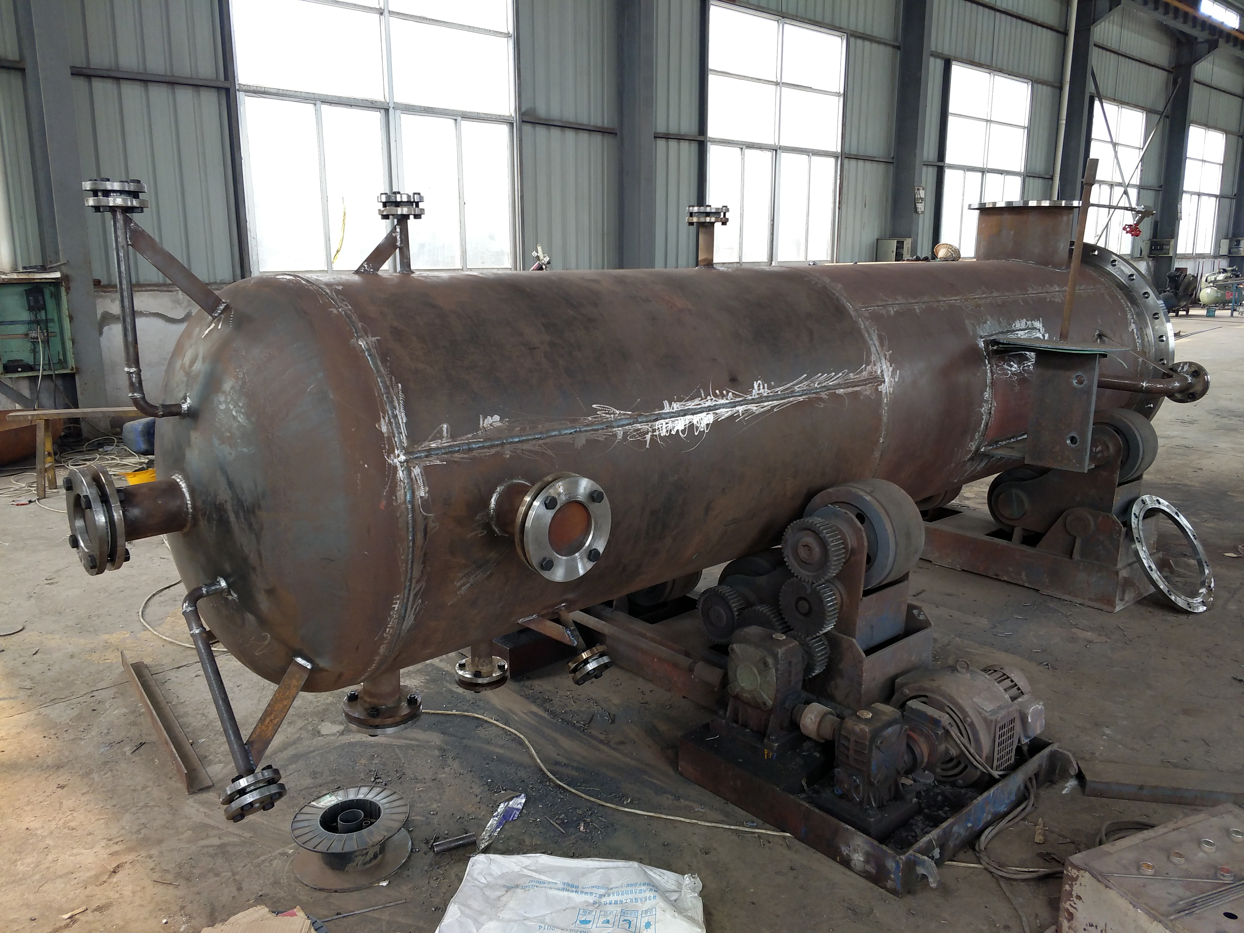
Assembly diagram of ball loading room
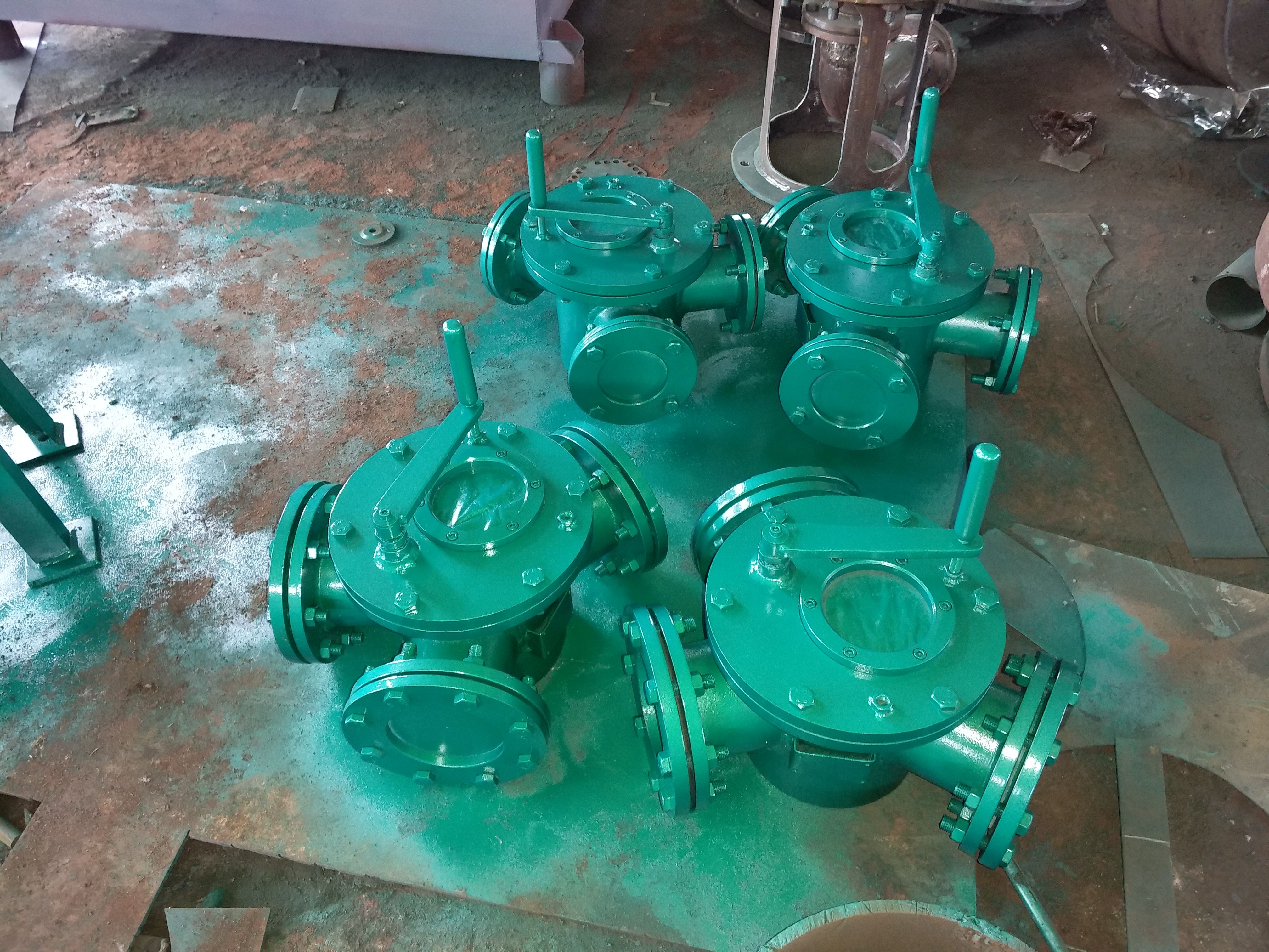
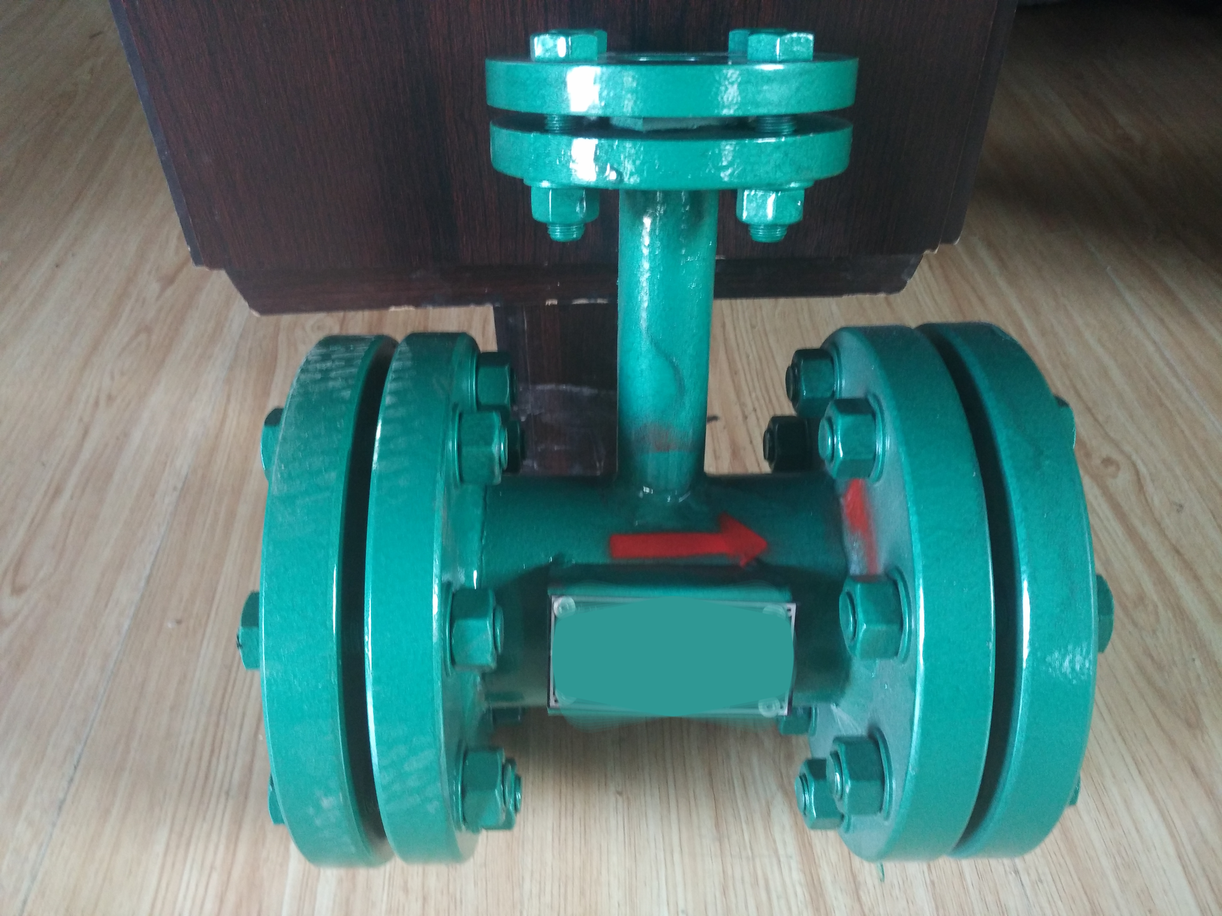
4. Splitter:
The manifold is a three-way (pipe) valve. By switching between its guide plate, the rubber ball can enter the side of the condenser that needs to be cleaned. It can also be used as a junction for the rubber ball outlet pipe of the ball collecting net and a diversion tee for the rubber ball pipe.
Splitter group diagram
5. Rubber ball pump:
Rubber ball pump
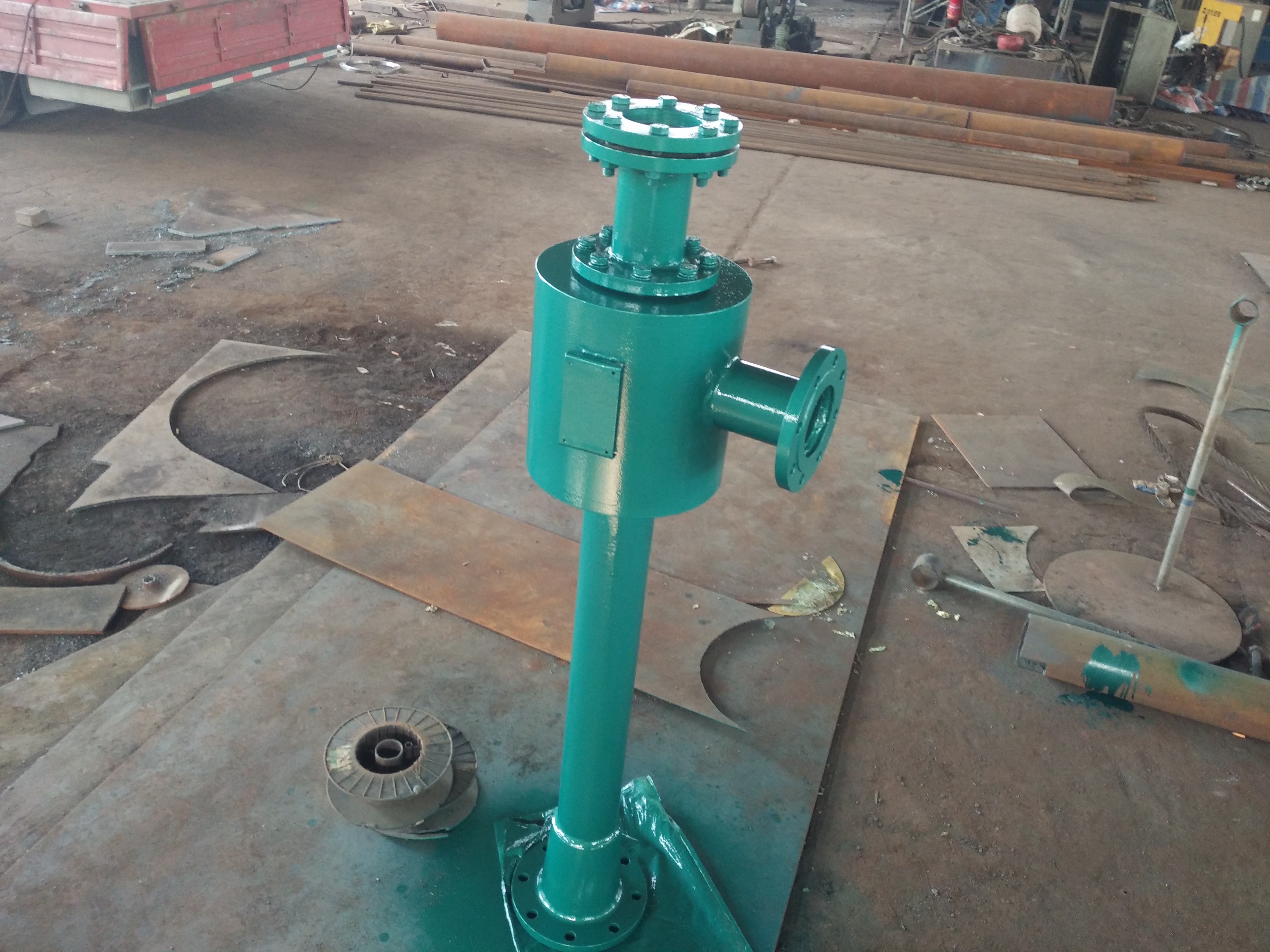
6. Main equipment of the rubber ball cleaning device (secondary filter):
-Function and type:
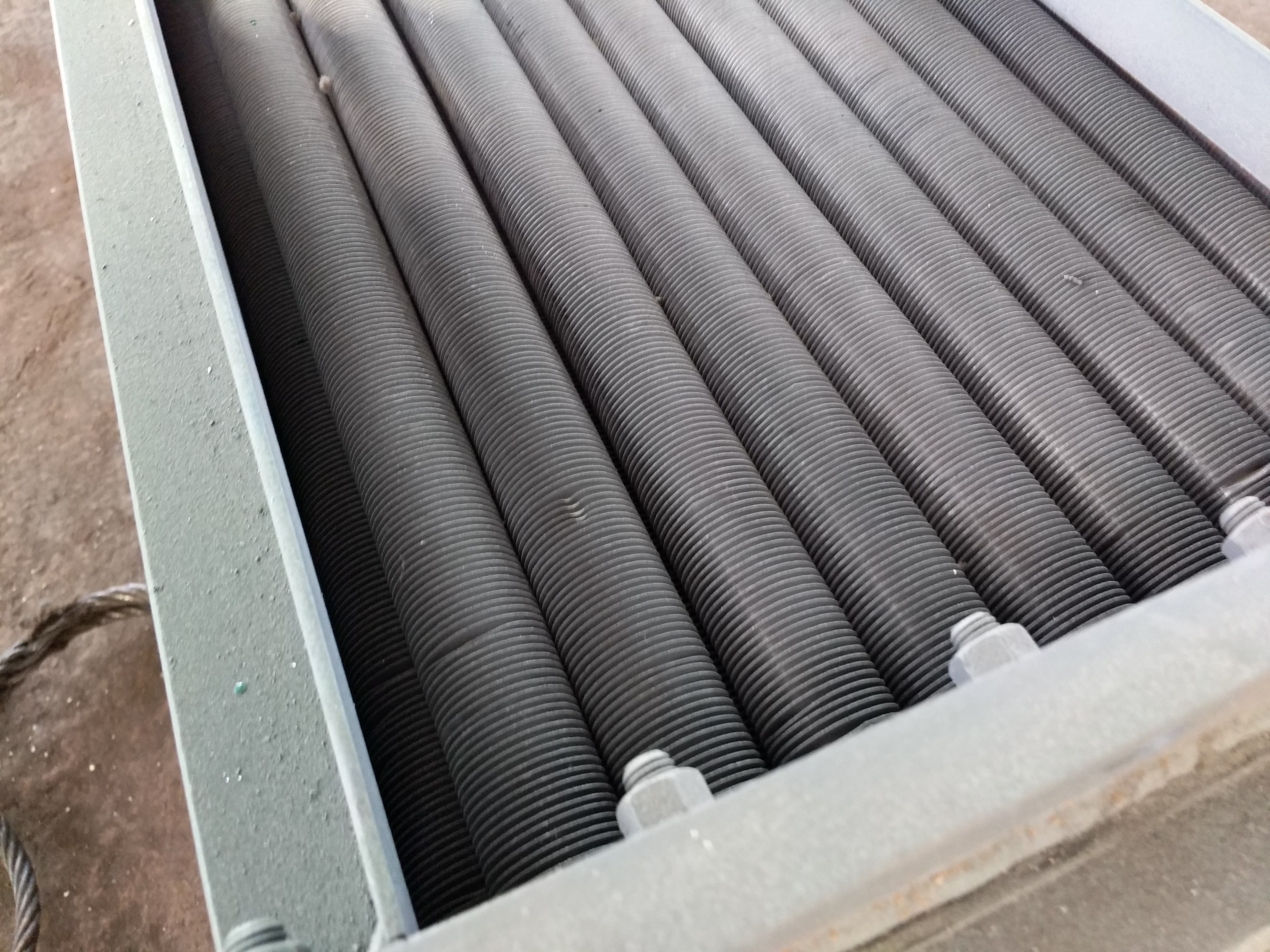
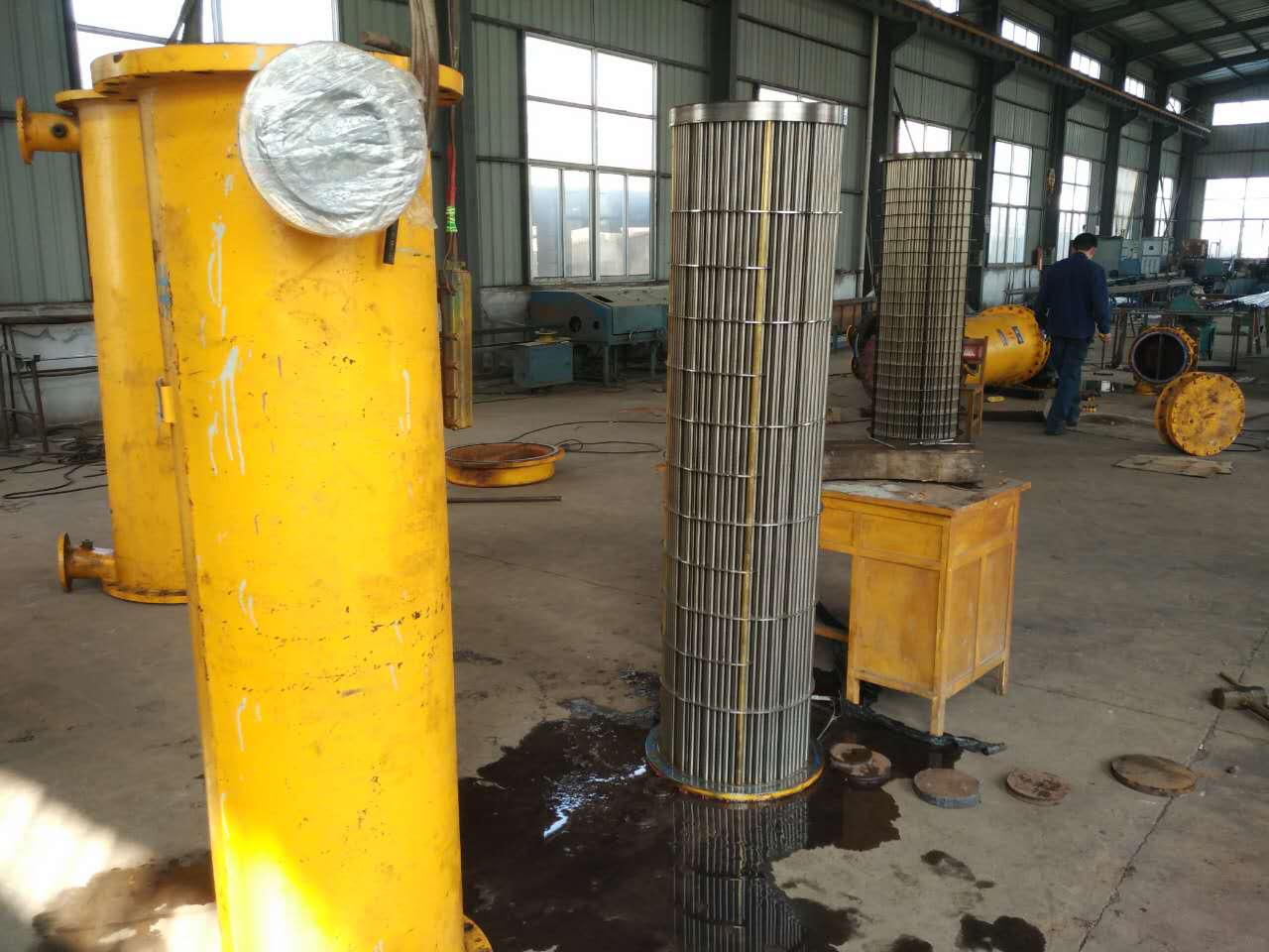
The secondary filter screen is one of the main equipment of the rubber ball cleaning device for condensers (steam turbine condensers). Its function is to filter cooling water, remove impurities that may clog the heat exchange tubes of the condenser, and ensure the normal input, recovery, and operation of sponge rubber balls. Especially in open cooling water systems with impurities and greatly affected by seasonal factors, the role of the secondary filter screen is particularly important. Secondary filters are divided into electric pressure backwash secondary filters, switching secondary filters, external rotating secondary filters, and other secondary filters according to their discharge forms.
2、 Model Description:
Electric pressure backwash secondary filter (DE series)
3、 The working principle of various models of electric pressure backwash secondary filters, switching secondary filters, external rotating secondary filters, and other secondary filters:
1. DE type fully enclosed electric pressure backwash secondary filter
The working principle of the DE type secondary filter screen: Cooling water flows from the outside of the mesh core to the inside of the mesh core, and impurities and dirt are attached to the outer wall of the mesh core. During cleaning, the electric drive drives the mesh core to rotate, and the drain valve opens. The accumulated debris on the mesh core is carried by the backwash water flow and discharged from the drain pipe outlet, which has the ability to clean the mesh core without stopping the machine. The amount of wastewater discharged during debris removal is less than 10% of the circulating water volume.
2. FE type switching backwash secondary filter screen
The FE type secondary filter adopts four mesh cores, and cooling water flows from the mesh core to the outside of the mesh core. Impurities and dirt accumulate inside the mesh core. When the pressure difference between the inside and outside of the mesh core is greater than a fixed value, the valve plates are operated one by one to rotate 90 degrees to cut off the cooling water entering the mesh core. At the same time, the drainage outlet is opened. At this time, the cooling water outside the (individual) mesh core flows into the mesh core, carrying impurities and dirt is discharged from the drainage outlet. The mesh core is cleaned one by one and then restored to normal operation.
Secondary filter screen usage:
The secondary filter is suitable for circulating water in the power industry, cooling water, and cooling water in industrial and mining enterprises, as well as other water pipes, to filter and clean water impurities.
Working principle of secondary filter screen:
After the secondary filter is connected to the pipeline system, water enters the secondary filter. When the amount of suspended solids, sediment, and other debris in the filter reaches a certain level, the water pressure difference between the inside and outside of the filter increases to the number of actions in the control system. The control system is activated, and the sewage discharge machine is put into operation to discharge the attached substances from the secondary filter. When the pressure difference outside the air returns to a positive value, the control machine is turned off and the filtration and sewage process is completed in a cyclic manner.
Secondary filter structure -:
1. Secondary filters are divided into vertical secondary filters and horizontal secondary filters according to their installation. They are divided into electric secondary filters and manual secondary filters according to their operation mode. They are also divided into electric pressure rotary backwash secondary filters and external rotation secondary filters according to their structure.
2. The working mode of the electric rotary recoil type secondary filter is that cooling water flows from the outside of the mesh core to the inside of the mesh core, and impurities and pollutants are attached to the outer wall of the mesh core. During cleaning, the electric drive drives the mesh core to rotate, and the discharge valve opens. The impurities accumulated on the mesh core are carried by the recoil water flow and discharged from the discharge pipe outlet, which has the ability to clean the mesh core without stopping the machine. The amount of wastewater discharged during debris removal is less than 10% of the circulating water volume.
3. The inlet water of the external rotating secondary filter flows from the outside of the mesh core to the inside of the mesh core, and the impurities in the circulating cooling water block and accumulate around the outside of the mesh core. When the pressure difference between the inside and outside of the network core reaches a fixed value, the drain valve can be opened and the electric butterfly valve can be turned from the fully open position to the guiding position (the electric butterfly valve is in the fully open state when it is in normal operation), causing the circulating cooling water to rapidly rotate and flow around the periphery of the network core, thereby flushing the debris accumulated outside the network core to the upper drain pipe for discharge. After cleaning and flushing, restore the butterfly valve to the fully open position and close the drain valve.
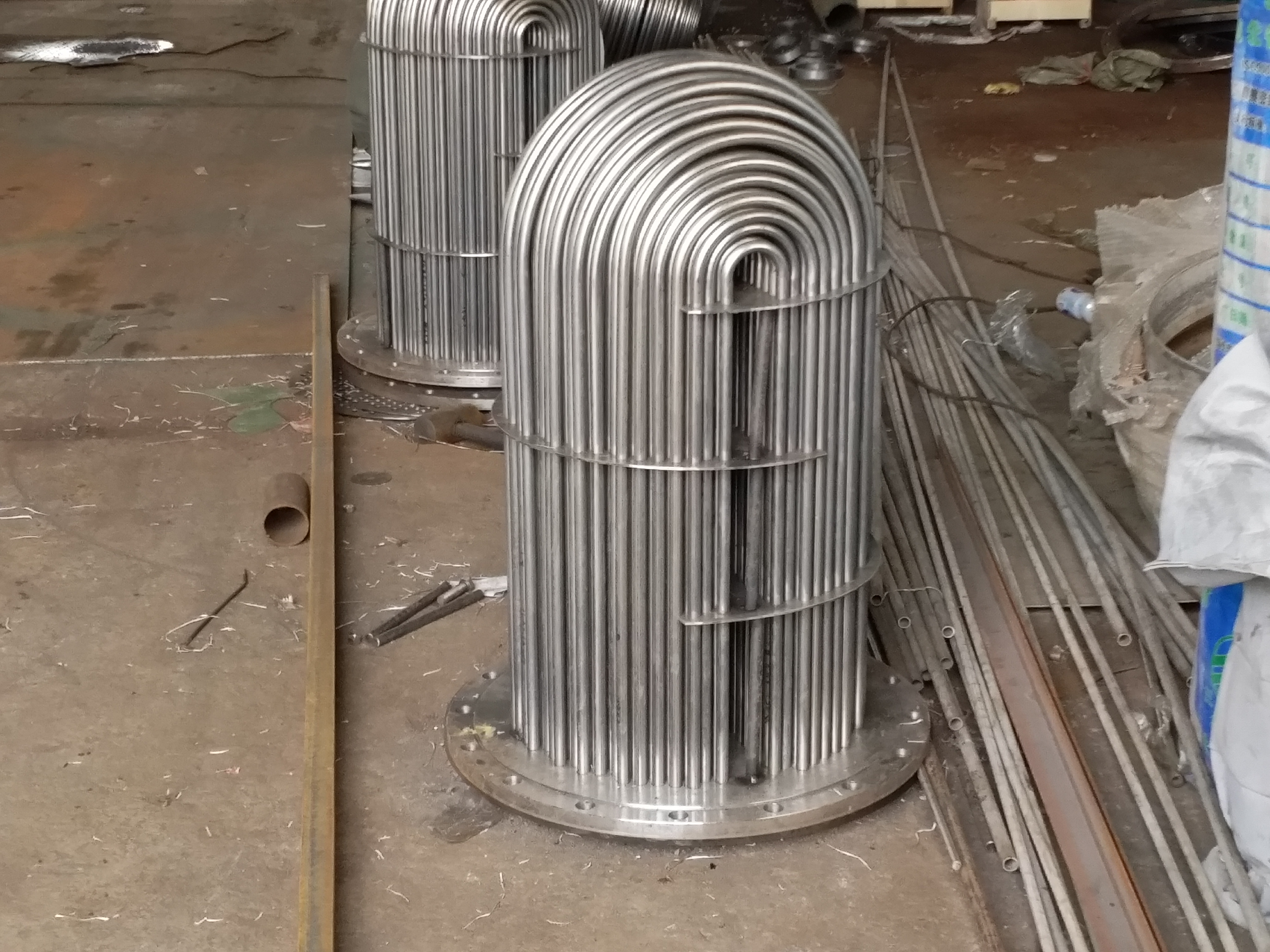
4. The secondary filter mainly consists of a shell, a stainless steel mesh core, a transmission motor, a reducer, and a drain valve. The filter is composed of a skeleton, mesh plate, and rib plate welded together, and the entire filter has sufficient rigidity and strength. The material of the mesh plate is stainless steel, welded to the framework, and the diameter of the holes drilled on the mesh plate is Φ 5 mm~ Φ 10 mm.
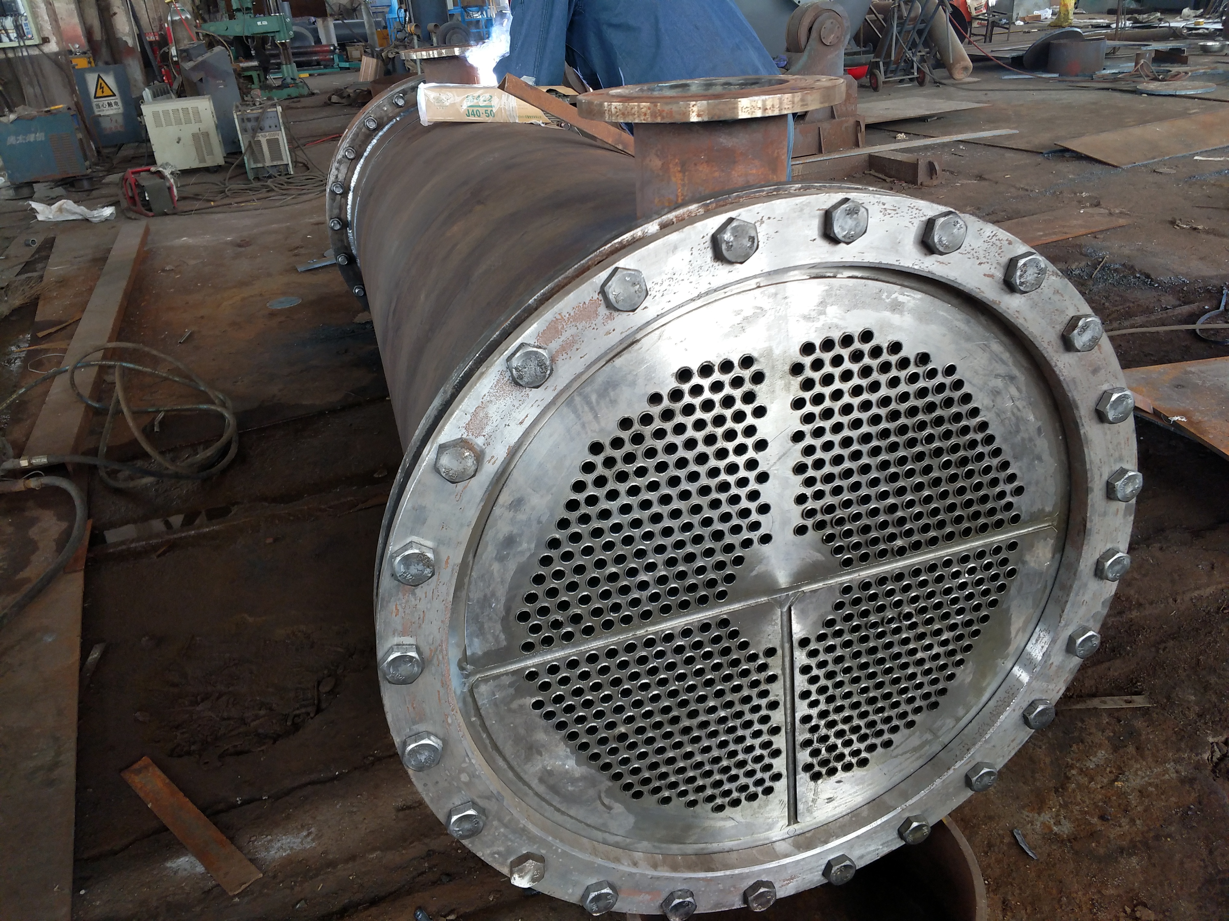
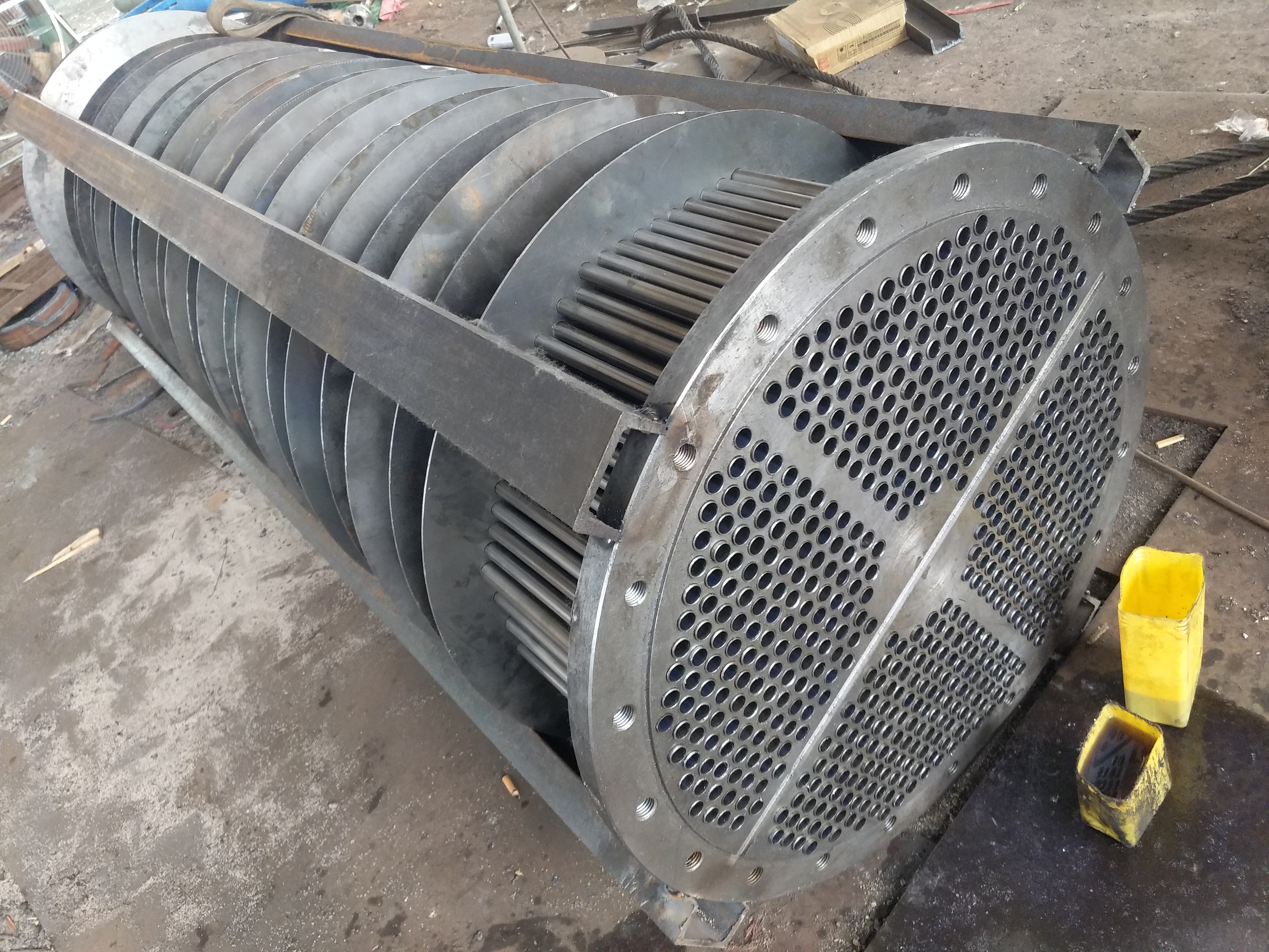
Secondary filter screen assembly diagram
Rubber ball cleaning device - outlet:
As an important means to improve the operation rate of power plants, the in situ condenser ball cleaning system has become a standard configuration in power plants, and the ball failure is a key element of this system. Suitable for grinding, with a soft and elastic texture, uniform material, suitable hardness, and uniform air to air penetration. The wet to air ratio is -1.00-1.15. At a water temperature of 5-45 ℃, the inner diameter of the ball is not large and does not melt during use. When using, the diameter of the wet ball is generally 1.0-2.0mm larger than the inner diameter of the cooling pipe. When there are two specifications of the cooling pipe, the smaller one shall prevail. When installing a sleeve at the cooling pipe mouth, the rubber ball shall be selected based on the sleeve.
(1) The amount of ball thrown is 7% -13% of the number of single side single flow cooling pipes in the condenser. Depending on the length of time required for the rubber ball to circulate, the lower or upper limit or its approximate value is taken. The time for the rubber ball to circulate is generally limited to 30 seconds.
(2) The rubber ball replenishment cycle or replacement cycle is a cumulative operation of the rubber ball cleaning system for 7 times. The replenishment cycle can also be adjusted according to the specific situation of the unit. The rubber ball replacement cycle, based on the production and use of the ball, is a cumulative operation of 60 rubber ball cleaning systems. In addition, after soaking in water for a certain period of time, some rubber balls may swell too much, resulting in a diameter difference. When replenishing and replacing the rubber balls, they should be replaced in a timely manner to prevent the cooling pipes from being blocked.
Working principle of rubber ball cleaning device:
1. The gap between the water chamber and the baffle of the condenser should be eliminated to cause a short circuit in the circulating water, and some balls should stay at this gap. Water chamber - Except for the inlet and outlet of circulating water, all external pipelines or blind holes need to be equipped with spherical mesh covers with a diameter of no less than 7mm at the inner wall pipe opening of the water chamber to prevent ball escape.
2. Circulating water flow rate - maintained at the design value with a deviation not exceeding+15%. The control range of the above values can also be adjusted appropriately based on operating experience. Rubber ball cleaning system - operation
Preparation for commissioning of rubber ball cleaning device:
1) Soak the rubber balls in warm water for 24 hours, and do not remove any unqualified balls after soaking.
2) Adding balls: Open the air release valve and water discharge valve of the ball loading chamber, open the upper cover of the ball loading chamber, put in the foam ball, and then press the upper cover to close the air release valve and water discharge valve.
3) Exhaust, open the water outlet valve of the ball loading chamber, open the exhaust valve, exhaust the air in the ball loading chamber until it flows out, and close the exhaust valve and drain valve.
Operation of rubber ball cleaning device:
Turn the handwheel of the ball collecting net to the "receiving position". Open the rubber ball pump valve and start the rubber ball pump. Open the outlet valve of the ball loading chamber and turn the switching valve of the ball loading chamber to the "cleaning position". Clean the system for 30 minutes
Rubber ball cleaning device system - stop operation:
Turn the switching valve of the ball loading chamber to the "receiving position", close the outlet valve of the rubber ball pump, stop the rubber ball pump, close the outlet valve of the ball loading chamber, close the rubber ball pump valve, and rotate the collecting wheel of the ball collecting net to the "net plate backwashing" position. At this time, the water flow backwashes the net plate and runs it.
Technical parameters of rubber ball cleaning device (various supporting equipment):
Collecting net specifications and models:
| 产品名称 | 产品型号 | 接管通径A1 | 网芯材质 | 产品高度H1 | 备注 |
| 手动单板式收球网 | SD-400 | ф426x6 | 1Cr18Ni9Ti | 1150 | 订货时须提供管径内外径尺寸及连接法兰接口尺寸,当循环水管径大于DN700并说明是否要电动-机- |
| SD-500 | ф529x6 | 1300 |
| SD-600 | ф630x6 | 1600 |
| SD-700 | ф720x7 | 1800 |
| SD-800 | ф820x7 | 1800 |
| SD-900 | ф920x7 | 1800 |
| 电动双板式收球网 | SF-8 | ф820x7 | 1800 |
| SF-9 | ф920x7 | 1800 |
| SF-10 | ф1020x8 | 1900 |
| SF-12 | ф1220x8 | 2000 |
| SF-14 | ф1420x10 | 2000 |
| SF-16 | ф1620x11 | 2200 |
| 电动双板式加固型收球网 | SF-18 | ф1820x12 | 2200 |
| SF-20 | ф2020x12 | 2400 |
| SF-22 | ф2220x14 | 2400 |
二次滤网规格型号 :
| 二次滤网型号(-DN) | 二次滤网型式 | 长度 (mm)
(法兰连接) | -壳体直径(mm) | 排污管规格DN | 电动减速机功率
(kW) | 通流面积比 |
| WF-600(500) | 立式、卧式 | 700 | 1000 | 150 | 3 | 1:3.75 |
| WF-800(700) | 立式、卧式 | 800 | 1200 | 200 | 3 | 1:3.60 |
| WF-1000(900) | 立式、卧式 | 900 | 1400 | 200 | 3 | 1:3.60 |
| WF-1200(1100) | 立式、卧式 | 1000 | 1600 | 250 | 3 | 1:3.50 |
| WF-1400 | 立式、卧式 | 1100 | 1800 | 300 | 3 | 1:3.40 |
| WF-1600 | 立式、卧式 | 1200 | 2000 | 350 | 3 | 1:3.4 |
| WF-1800 | 立式、卧式 | 1300 | 2200 | 400 | 3.5 | 1:3.30 |
| WF-2000 | 立式、卧式 | 1400 | 2400 | 400 | 3.5 | 1:3.25 |
| WF-2200 | 立式、卧式 | 1400 | 2600 | 450 | 3.5 | 1:3.25 |
| WF-2400 | 立式、卧式 | 1500 | 2900 | 500 | 3.5 | 1:3.10 |
| WF-2600 | 立式、卧式 | 1600 | 3250 | 500 | 3.5 | 1:3.10 |
| WF-2800 | 立式、卧式 | 1700 | 3550 | 600 | 3.5 | 1:3.10 |
| WF-3000 | 立式、卧式 | 1800 | 3950 | 700 | 3.5 | 1:3.10
|
Instructions for ordering rubber ball cleaning devices:
1. Is the scope of the order a complete set of requirements or one of them.
2. Provide the inner and outer diameter dimensions of the circulating water pipe in the condenser and the inner diameter dimensions of the cooling pipe in the condenser.
3. Do you need an electric tennis net.
4. Generally, manufacturers adopt a shared system, which includes two ball collecting nets, two distributors, one ball loading room, one rubber ball pump, and one electrical cabinet (whether to equip secondary filters depends on water quality).
5. Design value of circulating water flow rate and water impurity content.
Attention: The technical specifications and parameters of the rubber ball cleaning device, manifold, rubber ball pump, valve, pipeline, ball collecting net, secondary filter screen, ball loading chamber, rubber ball conveying pump control cabinet are for reference only, and international design is the main focus