time:2021-08-20 09:20:44Views:
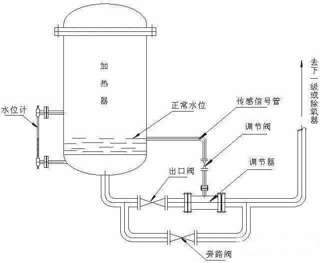
Structure of water level control device and working principle of gas-liquid two-phase flow:
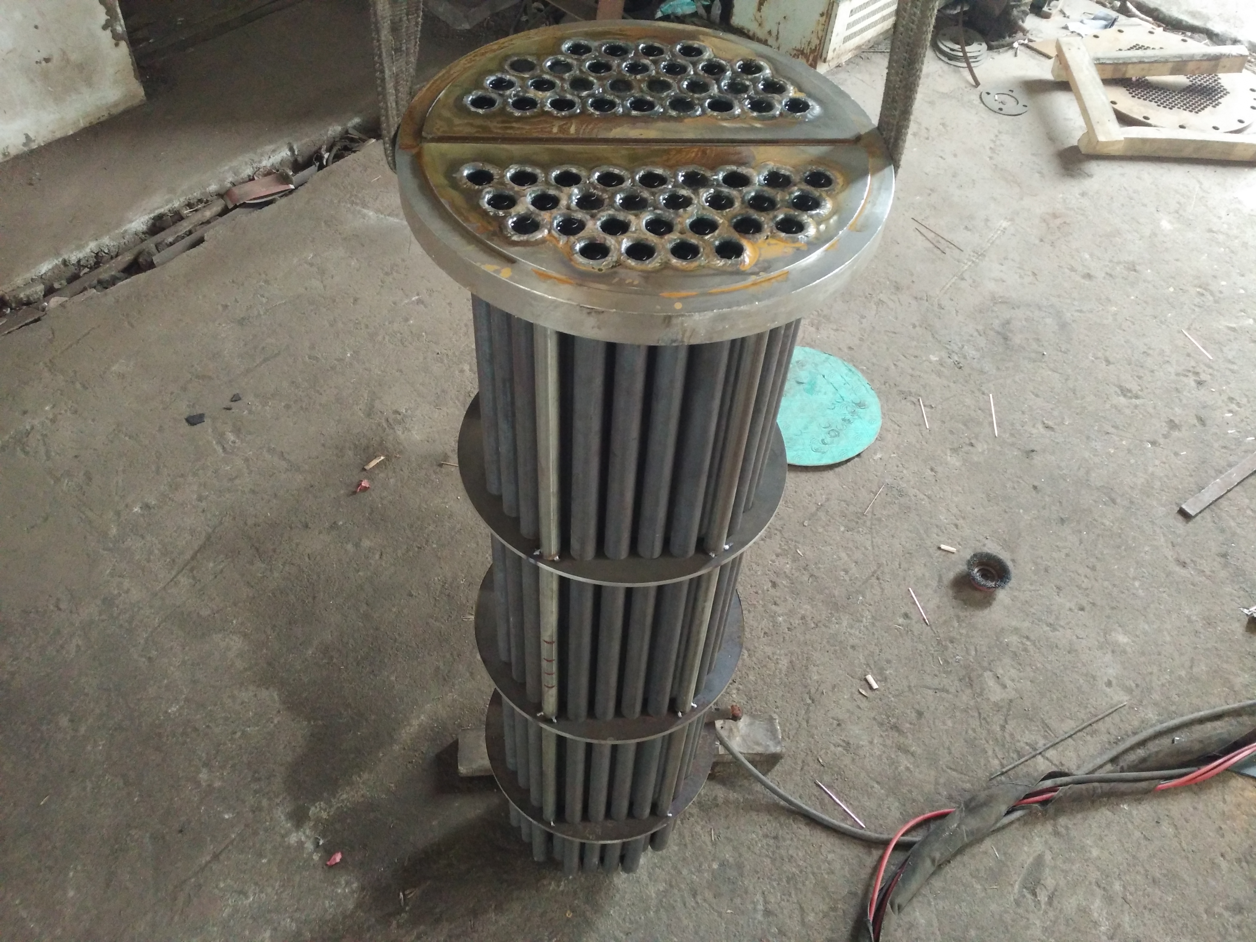
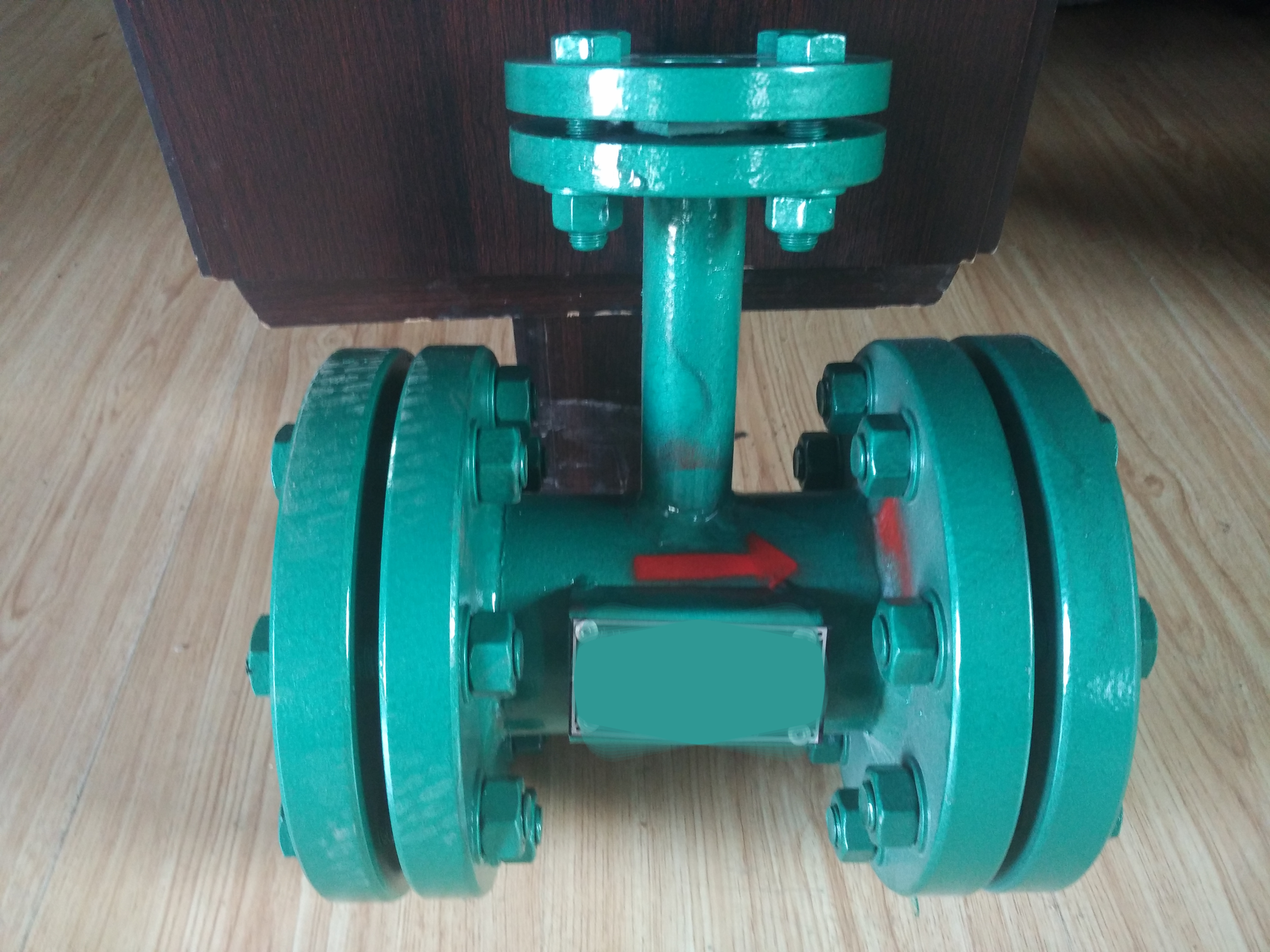
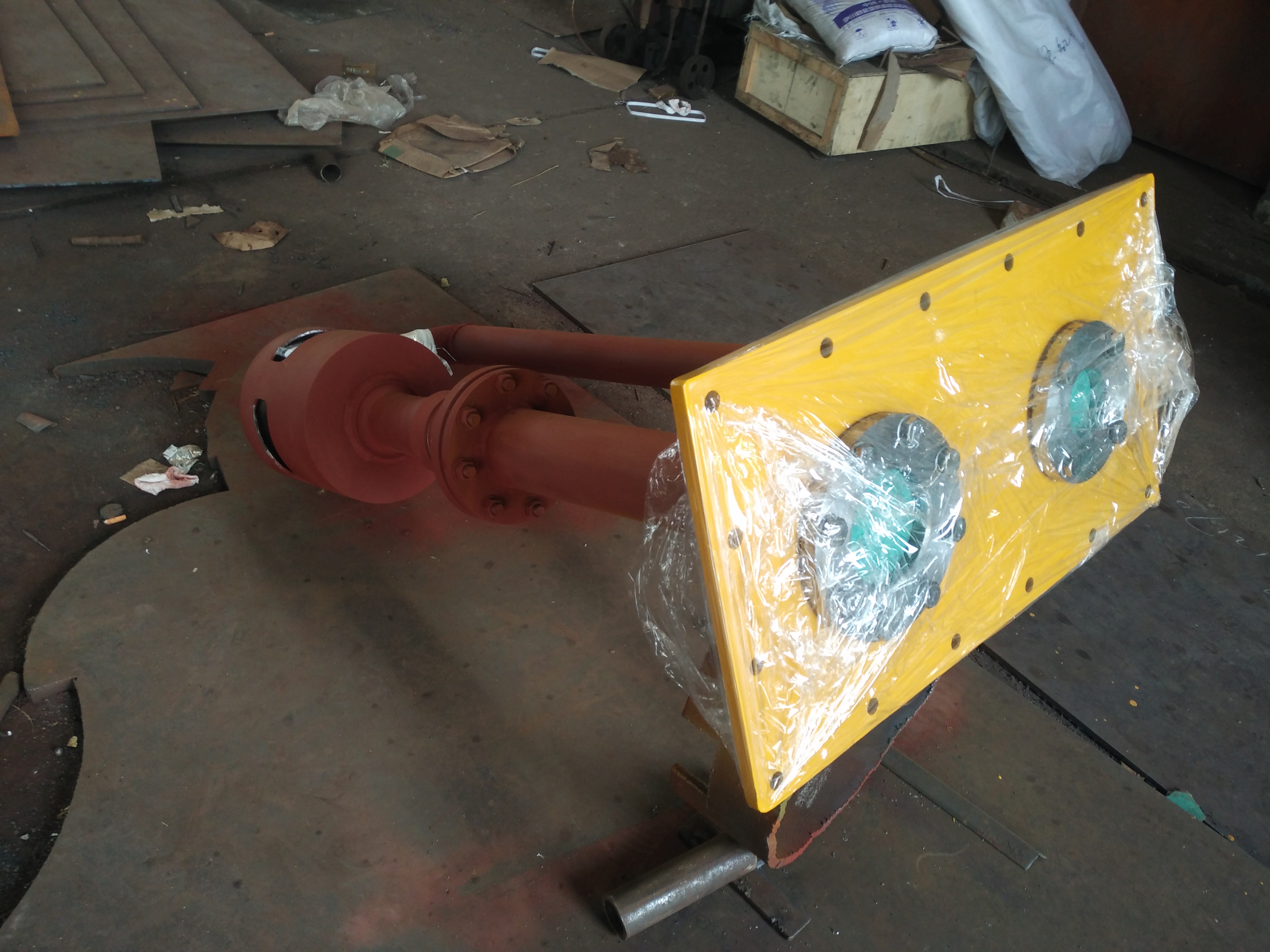
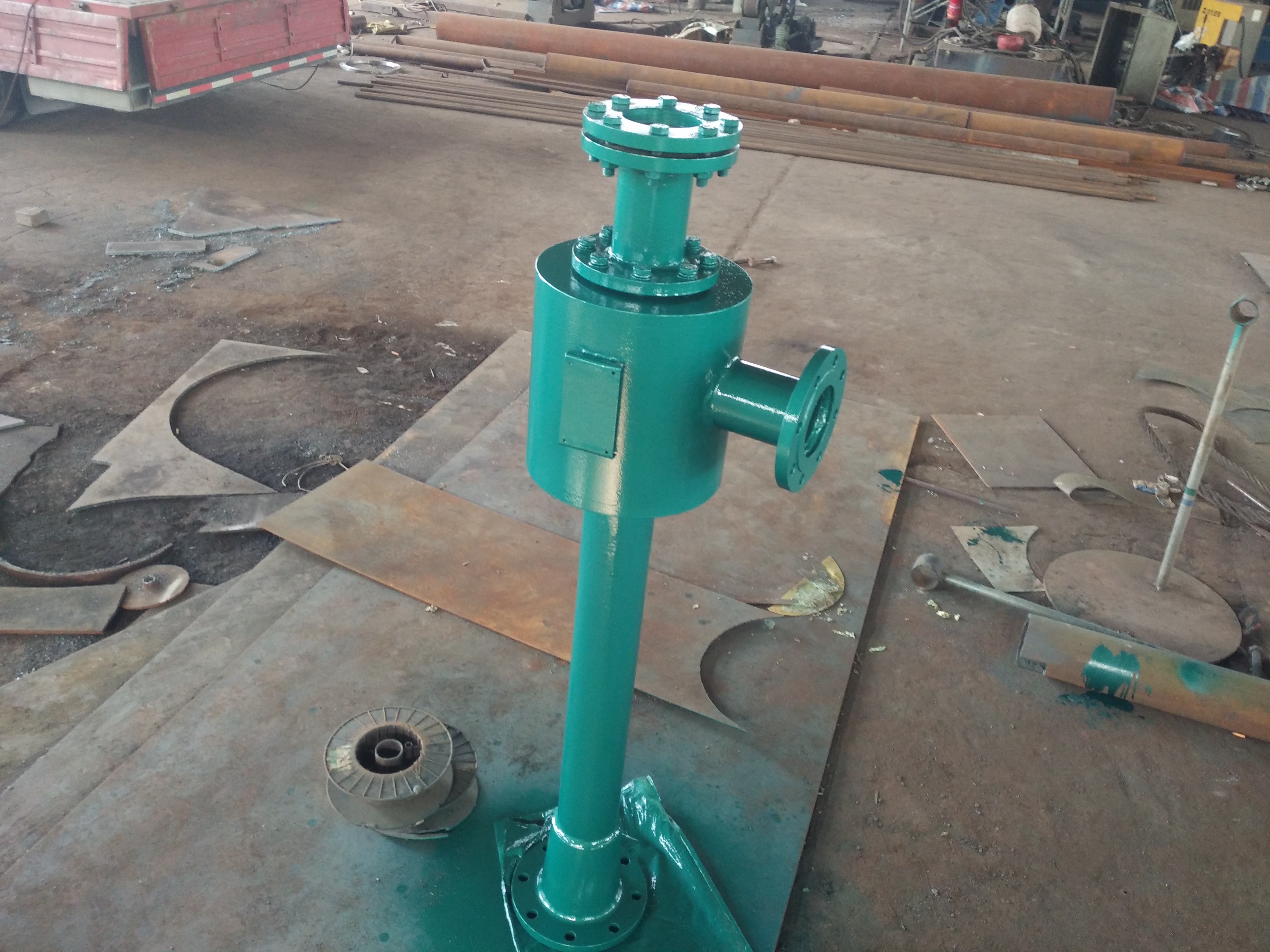
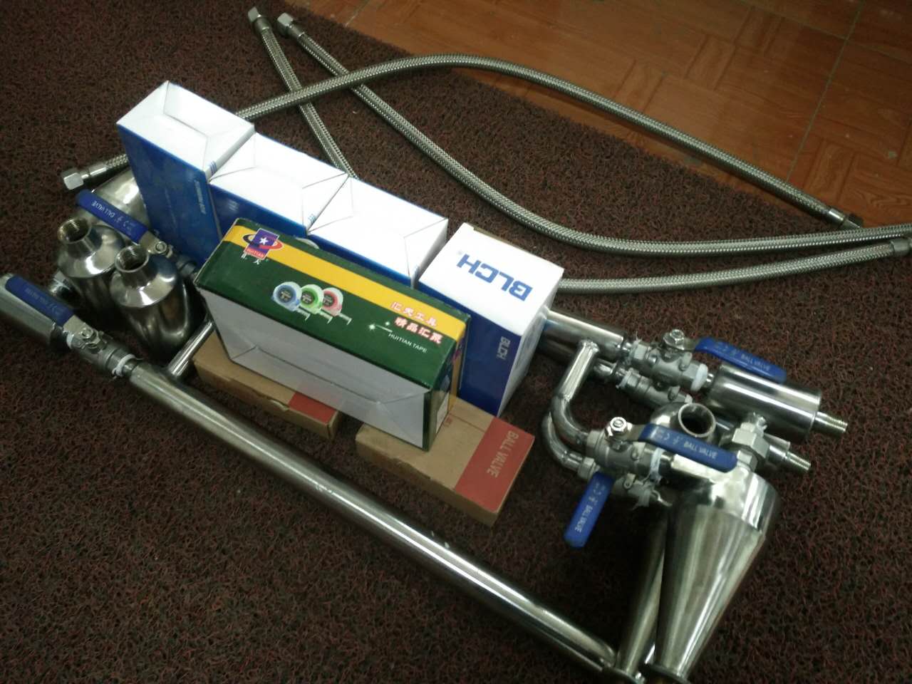
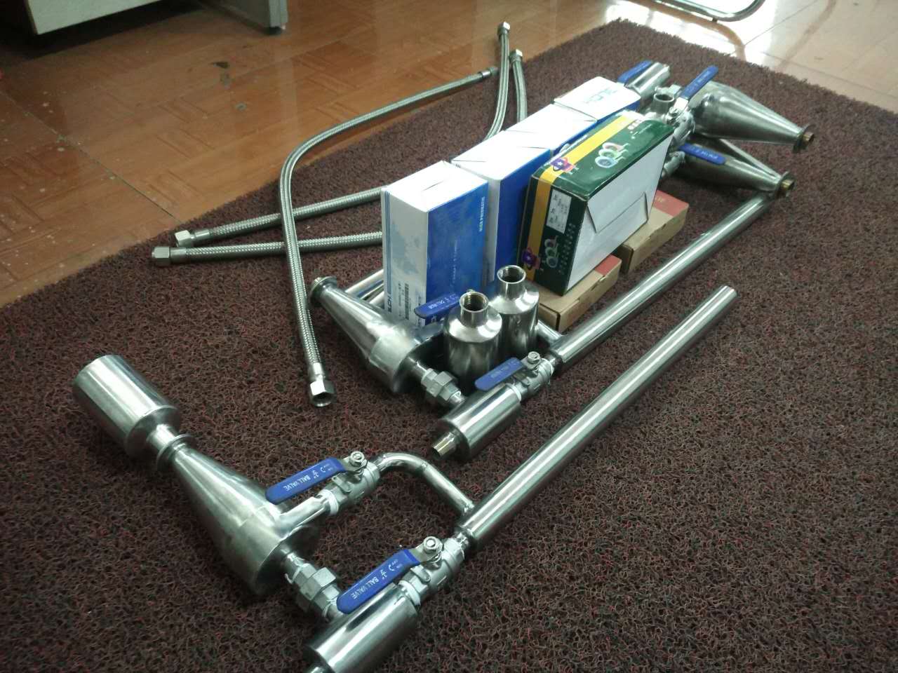
1. Structure of water level control device
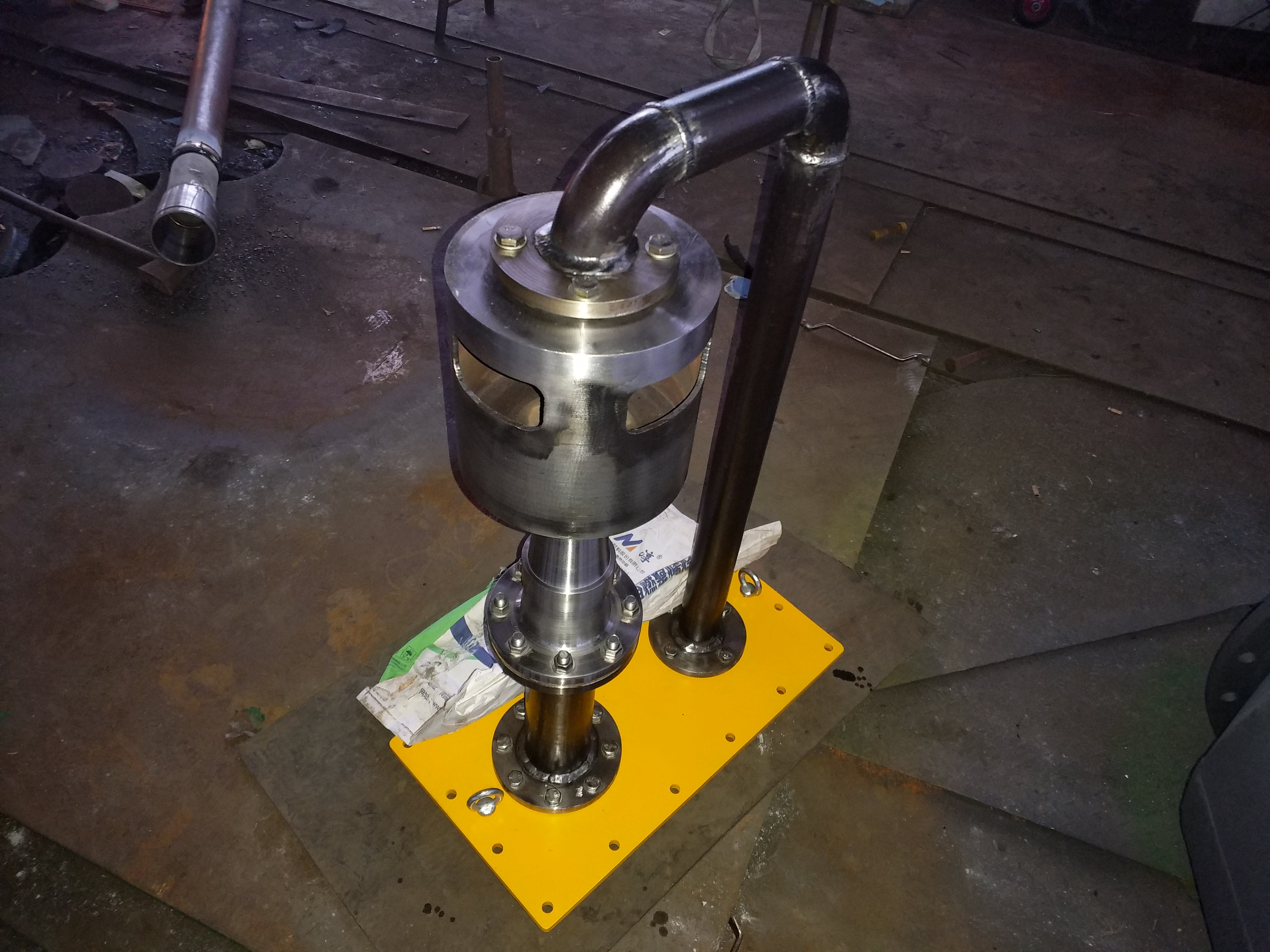
This device consists of a transmission signal tube and a regulator. The regulator is composed of a housing, connecting flanges, and a gradually shrinking and expanding valve core, with the regulating part being the regulating steam. Its function is to control the magnitude of hydrophobicity.
2. Working principle
When the water level in the heater rises, the corresponding water level in the signal tube also rises, resulting in a decrease in the flow area of the sending vapor, a decrease in the vapor flow rate in the regulating pipeline, and an increase in the liquid flow rate. This leads to a decrease in the vapor flow area at the throat of the regulating valve, an increase in the flow area of the drain, and a continuous increase in the discharge amount of the drain. Finally, a balance is established at the height of the drain water level, and vice versa.
-Mechanical drain valve:
Mechanical type, also known as float type, utilizes the temperature difference between condensate and steam, and through changes in condensate liquid level, the float lifts and drives the valve disc to open or close, achieving the purpose of blocking steam and draining water. Mechanical drain valves have low undercooling and are not affected by working pressure and temperature changes. They discharge water as soon as there is water, and there is no water stored in the heating equipment, which can achieve heat exchange efficiency- The high back pressure rate is 80%, which works well and is a drain valve for heating equipment in production processes.
Mechanical drain valves include free floating ball, free semi floating ball, lever floating ball, inverted bucket, etc
1. Free floating ball drain valve:
The structure of the free floating ball drain valve is simple, with only one movable component inside - a finely ground stainless steel hollow floating ball, which is both a float and an opening and closing part, and is a vulnerable part that can be used for a long time. The YQ drain valve has a Y-series automatic air exhaust device inside, which is non sensitive and can automatically exhaust air, working high.
The free semi floating ball drain valve only has one semi floating ball bucket as the moving component, with the opening facing downwards. The bucket is both an opening and closing component and a sealing component. The entire spherical surface can be sealed, used for a long time, can withstand water hammer, has no vulnerable parts, malfunctions, and can withstand steam leakage. The bucket pops open, the valve opens, and the air and low-temperature condensate are quickly discharged..
3. Rod float type drain valve:
The lever float type drain valve is basically the same as the free float type, with an internal structure where the float is connected to the lever to drive the valve core, and the valve is opened and closed as the condensate level rises and falls..
4. Inverted bucket drain valve:
The inverted bucket type drain valve has an inverted bucket as a liquid level sensitive component inside. The bucket opening is downward, and the inverted bucket is connected to a lever to drive the valve core to open and close the valve. The inverted bucket type drain valve can discharge air, is not afraid of water hammer, and is resistant to pollution.
5. Combination superheated steam drain valve:
The combined superheated steam drain valve has two isolated valve chambers, connected by two stainless steel pipes to the upper and lower valve chambers. It is a combination of floating ball and inverted bucket type drain valves. The valve structure is reasonable, and it can timely discharge the condensate formed when the superheated steam disappears under the working conditions of overheating, high pressure, and small load, effectively preventing the leakage of superheated steam and working high
2、 Thermostatic type drain valve:
This type of drain valve utilizes the temperature difference between steam and condensate to cause deformation or expansion of the temperature element, which drives the valve core to open and close. The subcooling degree of the thermal static type drain valve is relatively high, generally ranging from 15 degrees to 40 degrees. It can utilize some of the heat from the condensate water, and the valve always contains high-temperature condensate water, steam leakage, and energy-saving results. 1. Capsule type drain valve:
The main operating component of the diaphragm type drain valve is a metal diaphragm, which is filled with a liquid with a gasification temperature lower than the saturation temperature of water. There are two options to choose from: opening temperature - saturation temperature of 15 ℃ and 30 ℃. Guang.
2. Bellows type drain valve:
The stainless steel bellows of the valve core of the bellows type steam trap is filled with a liquid at the vaporization temperature and water saturation temperature. Control the valve switch with changes in steam temperature, which is equipped with adjustment bolts,
3. Bimetal plate drain valve:
The main component of a bimetallic sheet drain valve is the bimetallic sheet temperature element, which is heated and deformed with the rise and fall of steam temperature, and the valve is opened and closed by the valve core. 3、 Thermodynamic type drain valve
This type of drain valve, based on the phase change principle, relies on the different thermodynamic principles of flow rate and volume changes when steam and condensate pass through, causing different pressure differentials between the valve disc and the valve disc, driving the valve disc to open and close the valve
1. Thermodynamic drain valve:
There is a movable valve plate inside the thermal power type drain valve, which is both a sensitive component and an action component. According to the different thermodynamic principles of flow rate and volume changes when steam and condensate pass through, different pressure differentials are generated up and down the valve plate, which drives the valve plate to open and close the valve..
2. Disc steam insulation type drain valve:
The working principle of the disc type steam insulation type drain valve is the same as that of the thermal power type drain valve. It adds a layer of outer shell outside the steam chamber of the thermal power type drain valve. The inner chamber of the casing is connected to the steam pipeline, and the main steam chamber of the drain valve is insulated using the steam from the pipeline itself. Make it difficult for the temperature in the main steam chamber to cool down, maintain steam pressure, and tightly close the drain valve. When condensation water is generated in the pipe, the outer shell of the drain valve cools down, and the drain valve begins to drain; If no condensate is generated on the superheated steam pipe, the drain valve will not open and will operate high. The valve body is made of alloy steel, and the valve core is made of hard alloy. The valve has a high allowable temperature of 550 ℃, and has been used for a long time. It is a high-pressure and high-temperature steam trap valve.
3. Pulse type drain valve:
The pulse type steam trap has two orifice plates that adjust the valve opening and closing according to changes in steam pressure drop. Even if the valve is completely closed, the inlet and outlet are connected through two small holes, which are always in an incomplete closed state. Steam continuously escapes, resulting in a large amount of steam. The drain valve has a high operating frequency, severe wear, and a short duration. Small volume, water hammer, able to discharge air and saturated temperature water, close to continuous drainage, with a high back pressure of 25%, so it is rarely used.
4. Orifice plate drain valve:
The orifice plate type drain valve is designed to control the drainage volume by selecting orifice plates with different apertures based on different drainage volumes. The conclusion is simple. Improper selection may result in insufficient drainage or a large amount of steam leakage. It is not suitable for intermittent production steam equipment or steam equipment with large fluctuations in condensate water volume.
The principle of the substrate is that the hydrophobic material enters the valve chamber through the inlet of this device, and the phase change tube (signal tube) collects the vapor phase based on the liquid level. The liquid phase signal directly enters the valve chamber and flows through the designed throat after being combined with the hydrophobic material. When the liquid level drops, the vapor phase signal increases, reducing the flow area of the throat and reducing the hydrophobic flow rate, achieving the goal of hindering hydrophobic material. The liquid level can be automatically adjusted in a cyclic manner.
Debugging instructions for the self regulating control device of two-phase flow drainage liquid level
-Requirements:
1. The indication of the local water level gauge is clear, and the signal of the electrical connection water level gauge is accurate or incorrect;
2. High pressure heater protection action is stable and reliable;
3. The water level of other high-pressure heaters is stable, and any changes will affect the regulation effect;
4. Valve - internal leakage -, positive operation;
5. Emergency drain valve - leakage - (affects the amount of drainage).
2、 Test steps:
-Debugging must be carried out under high load:
1. Fully open the bypass gate, main regulating gate, and signal cylinder cut-off gate, and ensure the timing is correct-
Water level; If there is a water level, check if there is any blockage in the pipelines and valves.
2. Close the side door and still open the main control door; Possible situations: ⑴- The water level (or very low water level) indicates that it meets the operating parameters (the following three operations can be performed) If there is a water level and it is high, it indicates that there is a deviation between the design parameters and the operating parameters. The bypass valve must be opened again (to a lower water level, make corrections, and then continue with 3 operations).
3. Adjust the main regulating valve: gradually close it and the water level should slowly rise (at this time, slowly open the valve). Stop the operation when the water level approaches positive and observe the fluctuation of the water level If the water level fluctuates up and down within a certain range, it indicates that it has been adjusted and can be maintained at that position without further movement (if the water level is raised, it can be closed again) If the water level is unstable (rising or falling without returning to its original position), it means that it has not entered self adjustment and needs to be closed again. Open the valve to adjust until it stabilizes. If it is difficult to stabilize, analyze the reason (it may be due to large changes in upper drainage, or other factors such as large changes in steam volume and pressure).
3、 Adjustment - and low load test
Record the changes in water level under different loads, adjust the fluctuation range carefully, gradually reduce the load to a low load (economic operation of the unit with high pressure heater - low -) state, and verify the water level maintenance. If the water level is extended, adjust the main control valve to a certain level. When the water level gradually rises to a high load and does not reach the alarm limit, the test can be passed. If it reaches the limit, necessary corrections must be negotiated with the manufacturer.
4、 Notes:
The entire debugging work requires the approval of the shift supervisor and the operation of the turbine duty personnel. Prepare for accidents involving high water filling. In case of other accidents with the unit, stop the test and exit the site.
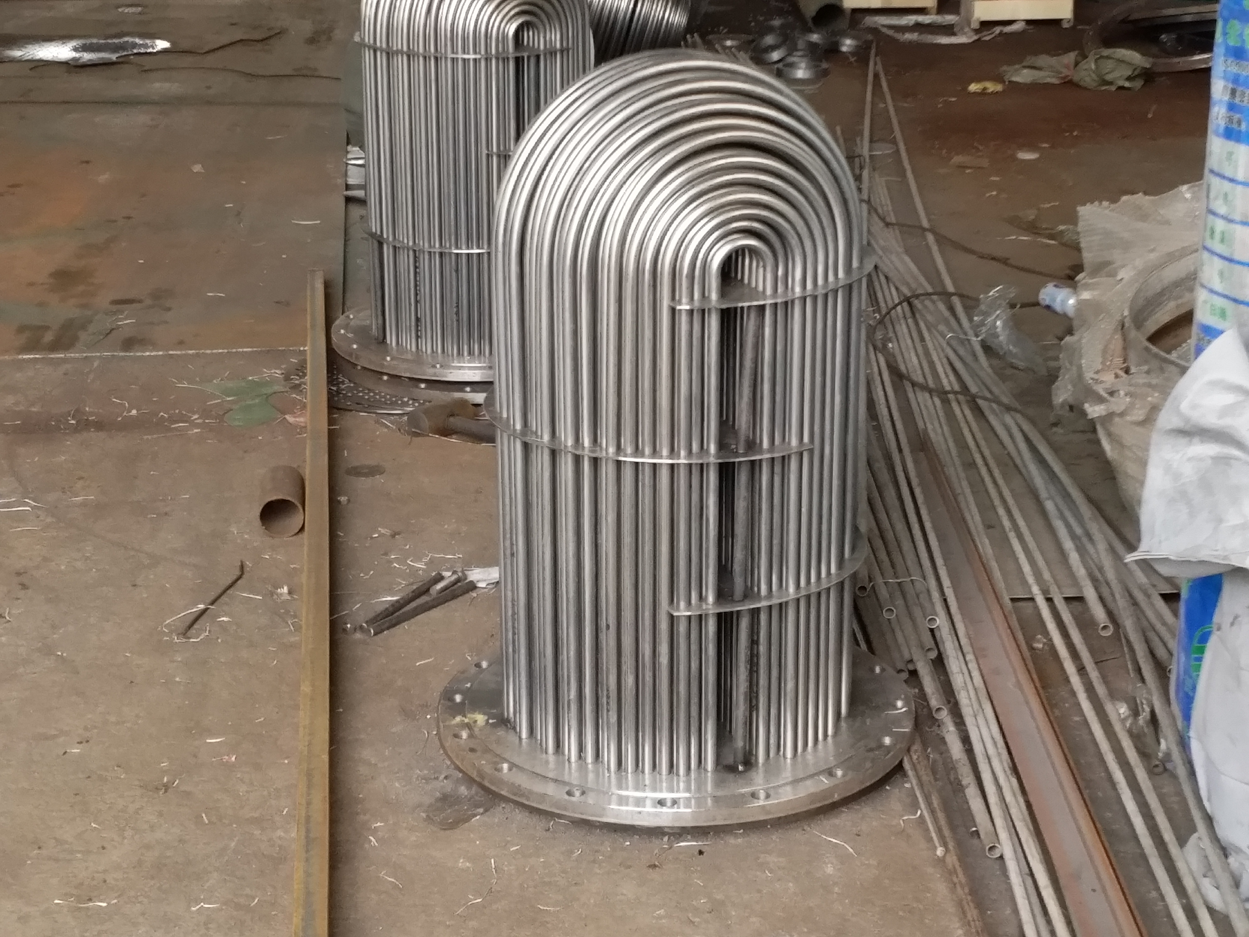
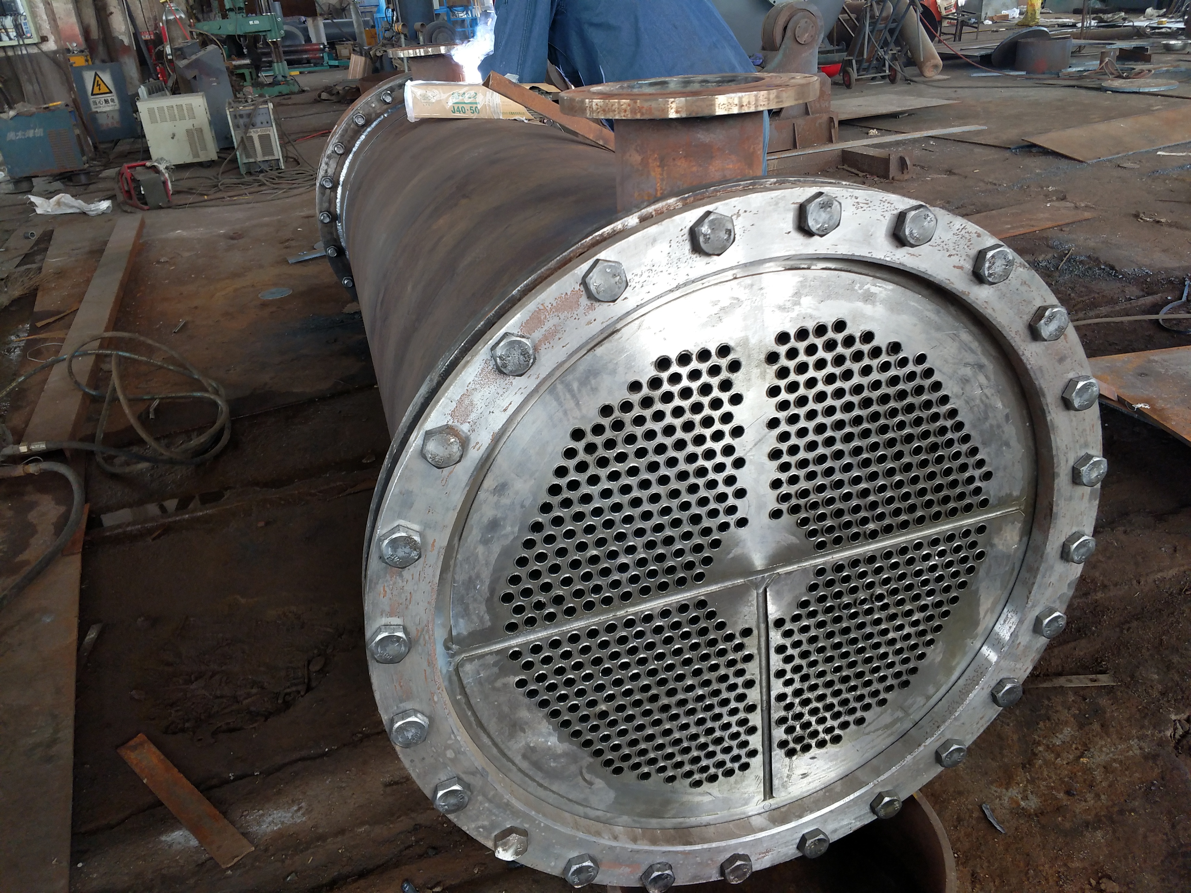
The steam seal heater adopts a horizontal U-shaped surface heat exchan...

The steam seal cooler generally adopts a horizontal U-shaped surface h...
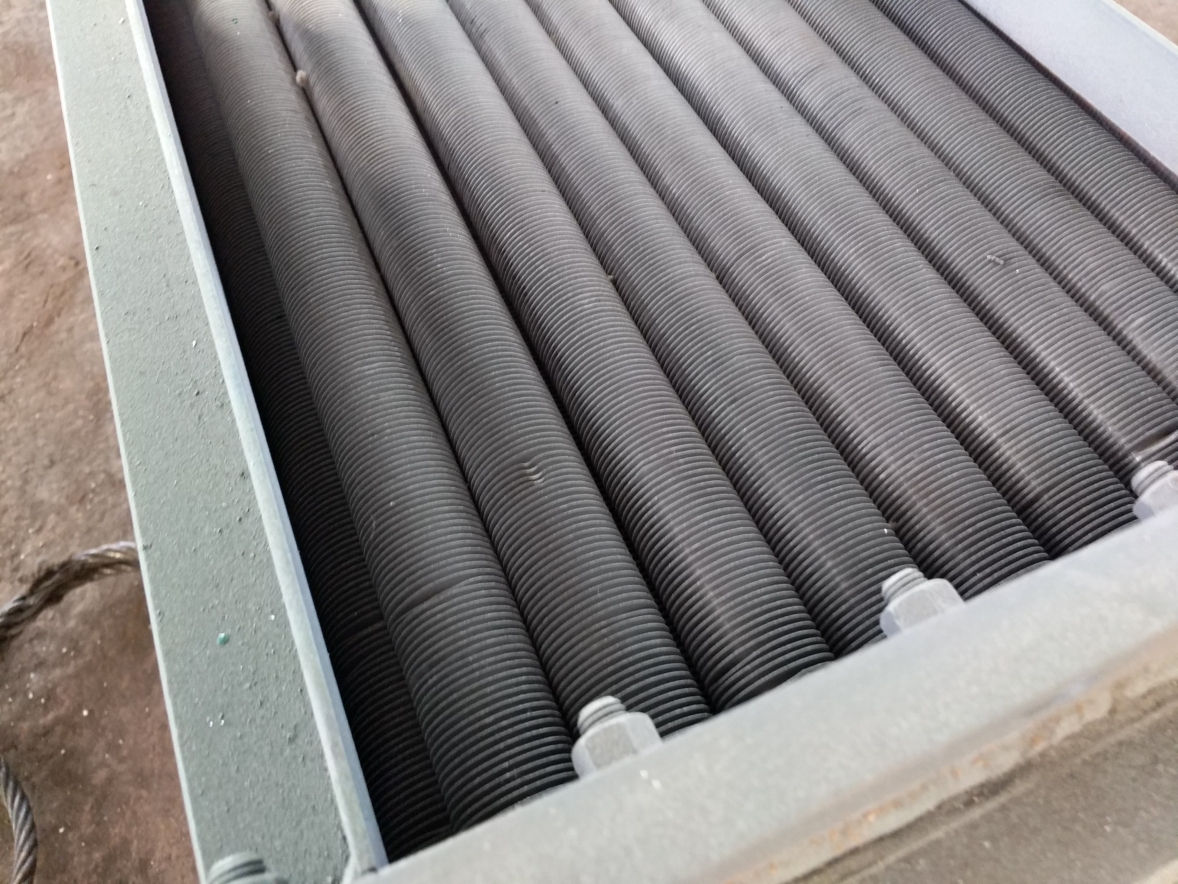
The air cooler adopts finned tube material, single metal finned tube a...
The waste heat recovery device, also known as the energy collector and...
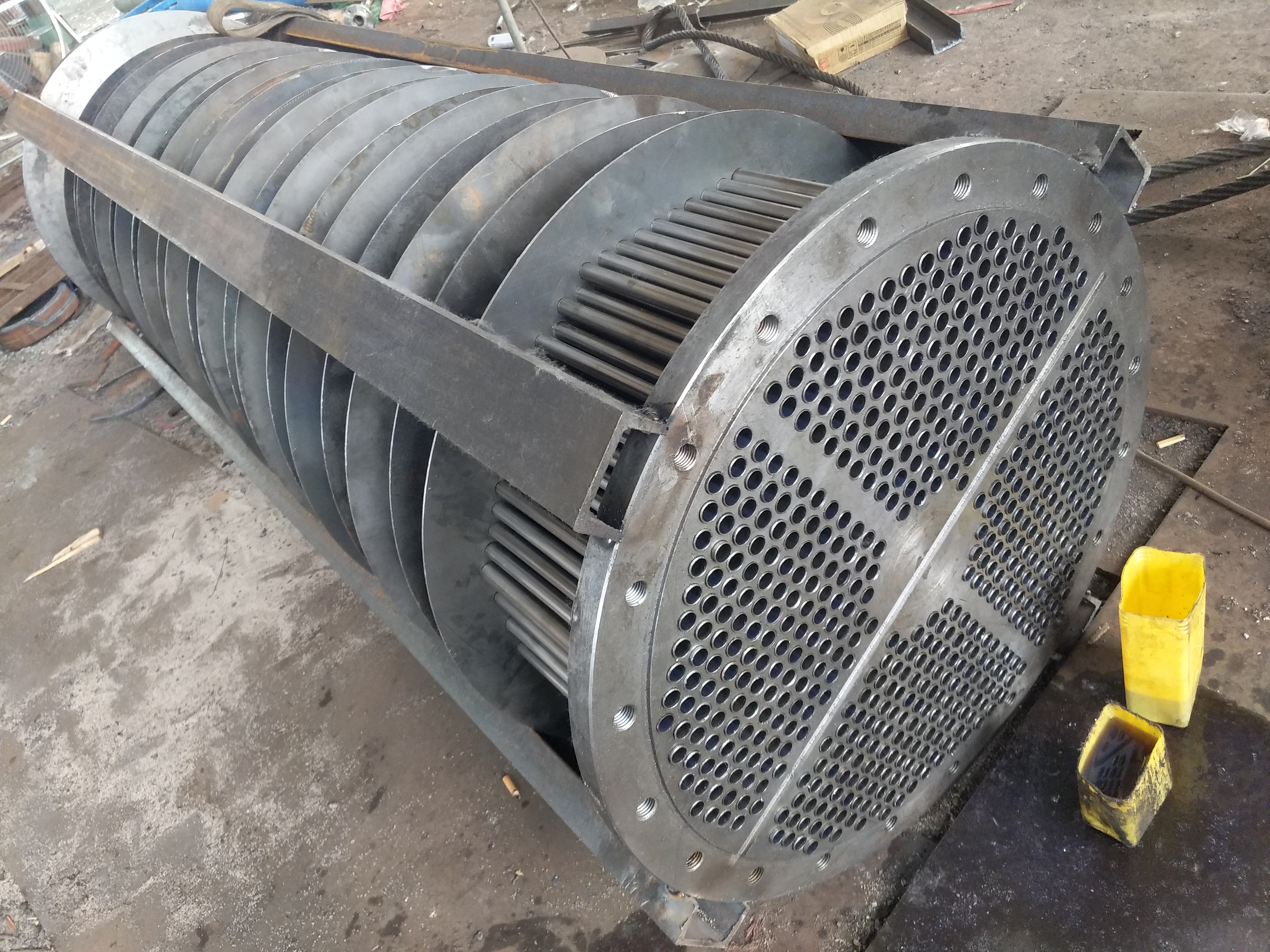
The U-shaped tube is used as a cooling tube for heat exchange tubes, a...

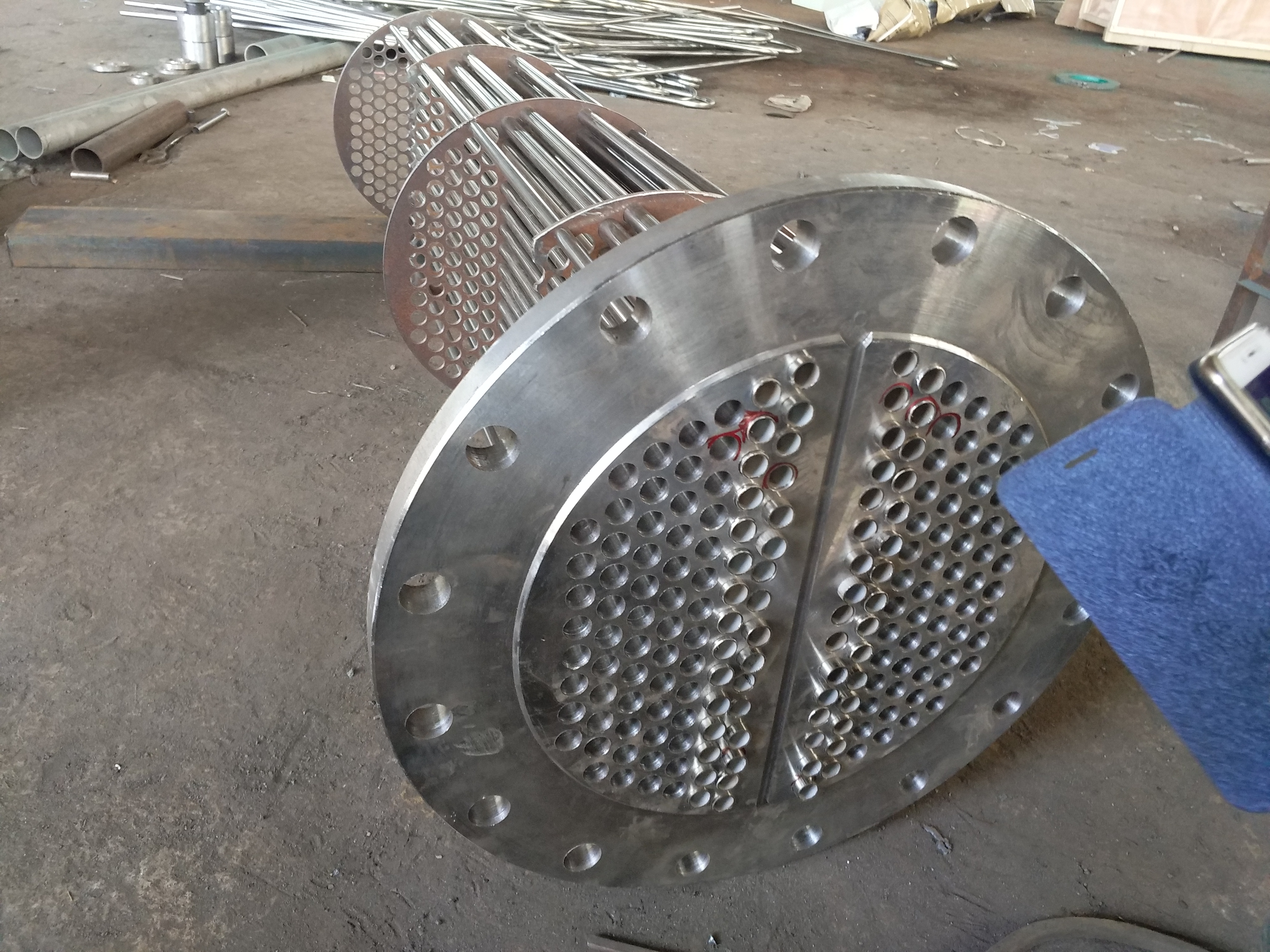
Overview of condenser tube replacement and condenser stainless steel t...
Welded steel pipes (also known as slotted pipes and welded pipes) are ...
Welded steel pipes (also known as slotted pipes and welded pipes) are ...
Manufacturer of shaft seal heaters, also undertaking pipe replacement ...
Welded steel pipes (also known as slotted pipes and welded pipes) are ...
Steam turbine oil-water cooler pipe replacement, marine oil-water cool...
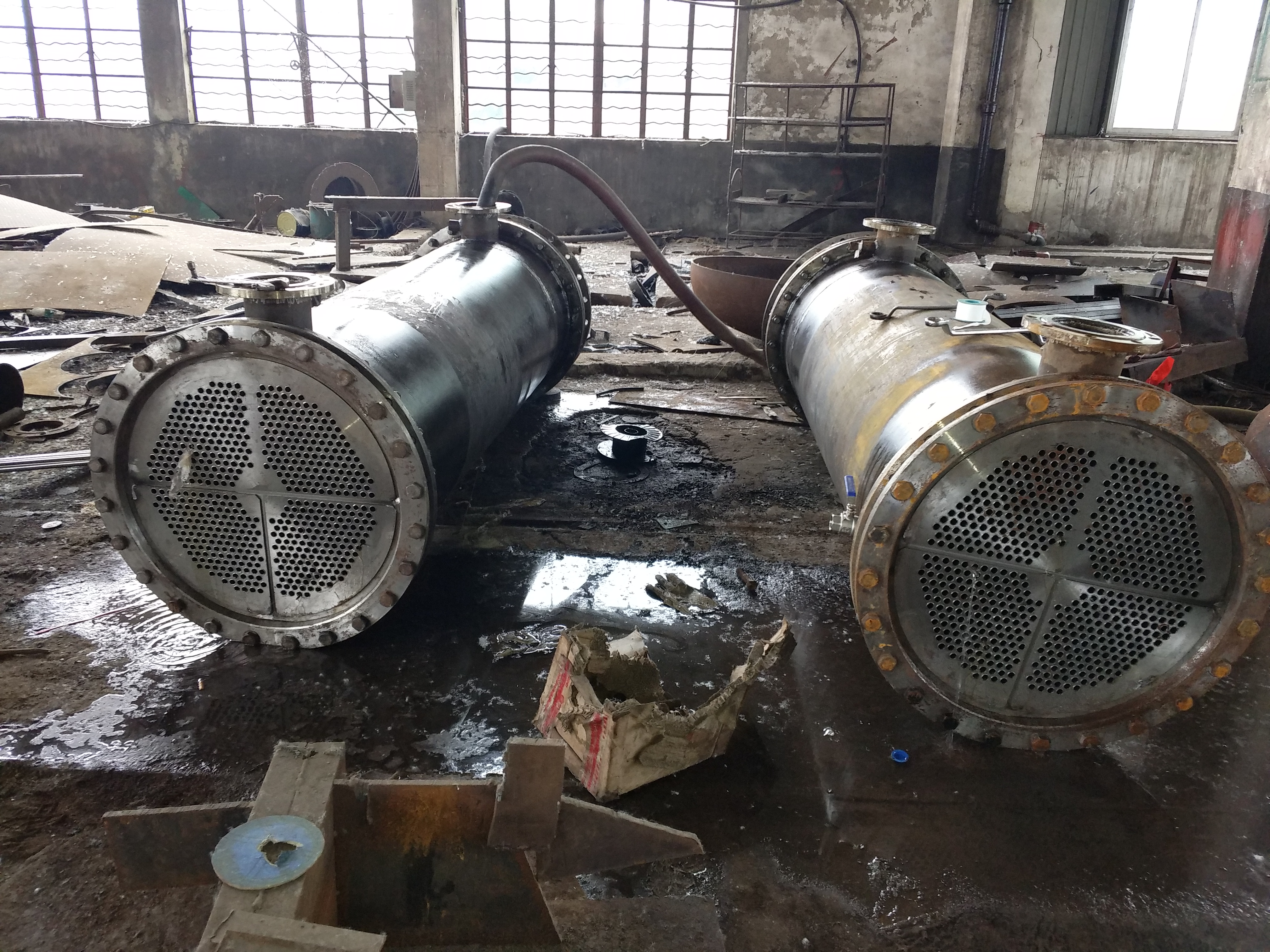
When purchasing a column type oil cooler for tube and core replacement...
The automatic steam liquid two-phase flow steam trap, also known as th...

The oil injectors produced by Lianyungang Lingdong Electromechanical E...
The oil injector is composed of a nozzle, a filter screen, an expansio...
A steam injector is a device that is powered by steam and is needed in...

Calculation of cooling area of sampling cooler 1: If the sample flow r...
The sampling of fly ash sampler is selected on the flue between the ou...
The use of carbon steel material in coal powder samplers has caused ma...
The working status of the oil injector and main oil pump, the analysis...

The oil supply and lubrication oil injectors are completely identical ...
The installation and operation of the coal powder sampler and mobile c...
The manual mobile coal powder sampler produced and manufactured by Lia...
The oil injector of Lianyungang Lingdong Electromechanical Equipment C...

Keep up on our always evolving product features and technology. Enter your e-mail and subscribe to our newsletter.
Copyright © 2012-2026 00LD连云港灵动机电设备有限公司遥遥制造汽液两相流液位自动疏水调节器、汽液两相流液位控制器、汽液两相流疏水器及油雾分离器、排油烟装置,可提供除氧器以及凝汽器换管改造、冷油器现场更换管束增容服务。 00ld.com 版权所有


